Thanks for the feedback and advice jean-paul, much appreciated.
I'll check again, I used a good amount of solder I thought but I can rewet again.Hi, the left board has dry joints at the coils
Yeah not nice. Didn't realise I'd ordered the wrong type till last night.and the TH resistor for R7 hurts the eyes a little 🙂
Okay will checkThe coils need slightly more solder.
You mean the resistors should touch the board? In which case flush is correct.Setting resistors should not be solder lifted from the board but they should be flush with the board (if that is the correct word).
Agreed, I only mentioned it in passing.C9 and R2 labels have been swapped indeed but since they're in parallel I did not bother to mention it and their sizes make things clear too.
Agreed. I was interested to see you'd specified a bleeder, but I use them as a matter of course with valves so just put it in.R2 is a bleeder only needed when the PSU is switched on and off regularly. None of my prototypes have it, I just added it for those that think the world is going down if bleeder resistors are not used.
Some arrived this morning with the heat sinks.You DO need desoldering braid to remove excess solder.
Mmmm, good point. Yes I was going to solder wires directly but you're right PCBs aren't as robust as point to point.Please use Phoenix MKDSN connectors for connections as I feel you will be soldering wires straight to the PCB ? I strongly suggest to not solder the wires straight to the PCB as it is gold plated and heat is transferred very good. You don't want tracks peeling off when you need to remove the wires for reasons that weren't planned.
Do you mean in my photos? If so can you expand please?To all, please read the text in the BOM, I have seen other mistakes
Ah okay. If I'm being honest I think I might have missed that if I hadn't traced the circuit out first. 😱
I'm just ordering the final connector X4 - WM4200-ND
I've not used this type of connector before so it's probably best to check - are these appropriate parts to go with it?
Housing WM2613-ND and crimp pins WM2625CT-ND
I've not used this type of connector before so it's probably best to check - are these appropriate parts to go with it?
Housing WM2613-ND and crimp pins WM2625CT-ND
I ordered and got that connector and it did NOT fit on the pcb (to big)...
Don´t wich one will fit..
Don´t wich one will fit..
It should be Molex KK 0.100 (=2.54 mm) 2 pin version. AFAIK it should be this one:
0022232021 Molex Inc | WM4200-ND | DigiKey
Ryssen, are you sure you ordered this one ? The original one in the BOM was the large one. Got a few of those too sent by Subbu and wondered what to do with them 😉
0022232021 Molex Inc | WM4200-ND | DigiKey
Ryssen, are you sure you ordered this one ? The original one in the BOM was the large one. Got a few of those too sent by Subbu and wondered what to do with them 😉
Last edited:
I just bought a Triad VPS10-2500 transformer. I see that it's a centre-tapped, and I'm unfamiliar with this.
As with all of my electronics projects, I will certainly connect the metal case of the transformer to chassis earth/PE, but should I also connect the centre tap to earth? If so, both connection tabs - the one on the primary side AND the one on the secondary side?
Thanks
As with all of my electronics projects, I will certainly connect the metal case of the transformer to chassis earth/PE, but should I also connect the centre tap to earth? If so, both connection tabs - the one on the primary side AND the one on the secondary side?
Thanks
Presumably you're using a Duet (9V)? If so, using the CT would give you two secondaries of 5V so not enough voltage. In this case simply connect the two secondaries in series to get a single winding of 10V, just as you will for the primary side to get 230V.
This link might help?
RECTIFIER CALCULATION
Edit - if I understand correctly you don't want to earth either 'CT', just connect them together on the tabs. So mains AC connects to tabs 1 and 6, and join 2 and 5. Then connect 7 and 12 to the AC inputs on the board, and join 8 and 11. NB this assumes this is your transformer
http://eu.mouser.com/Search/m_Produ...etics/VPS10-2500/&qs=VZvlzY8g9V9OxAoU4WdMmA==
Last edited:
I didn't explain the situation correctly.
I will be connecting tab 2 to tab 5 for series input of 240VAC, and I will be connecting tab 7 to 11 and tab 8 to 12 for 5VAC parallel output.
But in the middle of each strip of connectors there is an extra connection tab, which I think goes to the transformer core - and I think I have incorrectly referred to these as "centre tap".
I still want to know if these connection tabs should go to Protection Earth.
Difficult to say without knowing the transformer. The datasheet makes no mention of any connection for earthing the core so I'd be inclined to think those tabs aren't connected to anything. Perhaps drop Triad an email?I still want to know if these connection tabs should go to Protection Earth.
I built mine now,but I got an output of 8,82v target 9v.
Do you think the Duet will work fine with this?(Havent connected it yet)
Do you think the Duet will work fine with this?(Havent connected it yet)
Yes - it works just fine with this slightly lower voltage. You're only 2% lower than the target of 9v, which is close enough. If you feel like tweaking the voltage closer to 9v, then you can slightly reduce the value of R5(or R6). Putting a resistor with value between 75K to 100K in parallel with R5 (R6) should get you pretty close. But I don't think it's needed.I built mine now,but I got an output of 8,82v target 9v.
Do you think the Duet will work fine with this?(Havent connected it yet)
---Gary
Here is my finnished PSU:
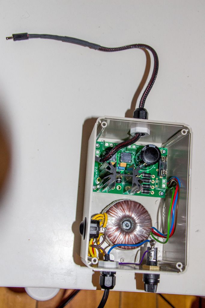
The heatsink does get a little hot during playback.
And it shure doesn´t sound worse than before..🙂
The heatsink does get a little hot during playback.
And it shure doesn´t sound worse than before..🙂
BTW Ryssen, nice build but I have to tell you to insulate the fuse holder at the primary side. It also helps to put the wires in the connector holes of the fuse holder and power switch and bend them a little so they form a "hook" before soldering. It gives a better connection and it is mechanically more sturdy (absolute best would be to use AMP crimping connectors).
Also no power LED which serves a a minimum load to keep the regulator working OK with no SB connected. You could have "wetted" the diodes at the upper side of the board a little with solder but that is just optics. Just telling you 🙂
Is that a 50 mm high heatsink ?
Also no power LED which serves a a minimum load to keep the regulator working OK with no SB connected. You could have "wetted" the diodes at the upper side of the board a little with solder but that is just optics. Just telling you 🙂
Is that a 50 mm high heatsink ?
Last edited:
OK, 2 x 9V in parallel. How much voltage does this toroid give in real life with this load ? And how much Ampere flows through the load ? I assume the top cover of the case is perforated or that is has at least some ventilation slots ? You could drill some 5 mm holes in the bottom of the case at the spot where the PCB is located to enhance cooling somewhat. For instance the exact locations where the holes are in the PCB. You will need 4 feet then for the case. As it is a linear regulator it will always be warm but hot is another matter. The heatsink must transfer the dissipated power to the air so optimal natural air flow is necessary (certainly when loaded with a high load and/or large difference between input and output voltage). No fans please.
Last edited:
- Status
- Not open for further replies.
- Home
- Amplifiers
- Power Supplies
- Building the SBT PSU