PT DCR isn't 1,195 ohms, this value is the source resistance. Also PSUDII not show any kind of problem.If I remember correctly, you use R.C. V9 regulators.
Rod recommended 3V voltage overhead for this.
If you use 8R as filament bias resistor, the recommended minimum raw voltage for R.C. regulator:
(1.25A*8R)+7.5V+3V= 20.5V
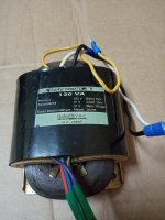
If the values in PSU (PT secondary voltage - 23.1V? -, PT DCR - 1.195R? - , chokes DCR) are correct, the secondary RMS current is 2.29A .. below the 2.4A .... but probably will overheat.
Rule of the thumb: use at least twice power (current) capacity transformer for large/r/ current as calculated.
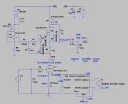
See schematic in #35 post.
Last edited:
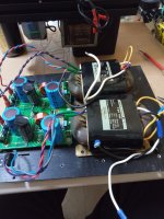
Bela changed the Rod Coleman regs V8 for V9, but there is something weird that puts my power amp off for self-protection.
I set up the V9 for 7,5V (as Rod Coleman said it's the most important thing once warmed up after 1 hour on), but one channel across 8R 10,739V = 1,342A
and the other channel across 8R 10,390 = 1,299A, both very high from 1.25A!!! but Rod said no problem.
Also Ale's Moglia hybrid mu-follower once set the anode voltage one channel mesured 30mA and the other 40mA, both very far from the 20mA!!!
Any idea what's happening to fix the issue?
10.739V vs. 10.390V is 3.36% difference.
Are you sure, that our 8R filament bias resistors (heated up to 50-70C case temperature) within this? I would be surprised.
The current on 8R filament bias resistor is: Ix= I(filament)+Ia
If the expected Ia is 20mA and If is 1250mA, the sum 1.27A.
On the exact value 8R this current causes 10.16V. See #83 post schematic.
1.) Set 10V on 8R filament bias resistor.
2.) Set anode voltage to (for example) 234V. Measure voltage on 8R filament bias resistor.
3.) Readjust 10.16V on 8R filament bias resistor by R.C. V9.
4.) Measure anode current on gyrator 10R resistor.
If the expected operating point about 220V, 20mA, about -14V (10.16V + half of filament voltage), the tube's operating point same as calculated.
BTW are you measured both tube in the same channel with same settings? If tubes are very different, the results will be the same.
If the tubes in same channel, with same settings produces close voltage, current parameters (for example within 5%), the tubes are OK.
If the tube in another channel, with same settings produces different results, something bad in the "another" channel.
Thanks Bela, I have more news: the problem that power off the amp is the right channel because when only connected the left channel the power amp doesn't power off.
The right channel is 8R 10,390V = 1,299A
The right channel is 8R 10,390V = 1,299A
Following your advice:
Right channel
15,70mA hybrid mu-follower
7,146V filaments voltage
8R - 10,16V = 1,27A
Left channel
16,72mA hybrid mu-follower
6,894V filaments voltage
8R - 10,16V = 1,27A
Filament bias resistors are 8R non inductive 1% https://www.mouser.es/ProductDetail/Vishay-Dale/NH0508R000FC02?qs=4m5JBqUW1O5yQAuEmwFM1Q==
Last edited:
- Home
- Amplifiers
- Tubes / Valves
- Building Euro21 801A tube preamp


