Polarity is correct. Cap voltage is correct (50V). The cabinet is not ventilated well, but these caps are warmer than the PS caps!
The simulation shows significant current through these caps though.
Can you attach your asc file?
I checked in my simulation - no current flowing through these caps...
Another possibility - are these authentic caps, or perhaps cheap/fake caps from Ebay, with advertised voltages higher than in reality? Like 25V caps sold as 50V caps?
These are authentic caps (samwha) that I use regularly. Attached is the .asc file.
BTW, the simulation in PSUD2 shows around 20mA through these caps.
In 28V voltage sources - set "Series Resistance" to 0 (or remove it completely),
and current flowing through the caps disappears.
So, I guess I have to remove R29, R30 and hope for a good enough local decoupling with just the C8, C9 caps. Or, do I reduce the value to 200uF as prescribed originally by Elvee?
Thanks for the experiment, Minek.
Thanks for the experiment, Minek.
Last edited:
So, I guess I have to remove R29, R30 and hope for a good enough local decoupling with just the C8, C9 caps. Or, do I reduce the value to 200uF as prescribed originally by Elvee?
Thanks for the experiment, Minek.
From my experience, I keep smaller (E.g 220uF + 100nF caps on the board), and of course big caps in the PSU.
I personally didn't see any difference in test/measerments/performance if I put big caps on the amp pcb.
Something is not logical here: heating these caps would require a large 100/120Hz current, or an even larger HF current.
Such a current would cause a massive dissipation in the OP's, which should be noticeable.
You should look at the rails with a scope: if an AC current causes the heating, an AC voltage should be visible.
Such a current would cause a massive dissipation in the OP's, which should be noticeable.
You should look at the rails with a scope: if an AC current causes the heating, an AC voltage should be visible.
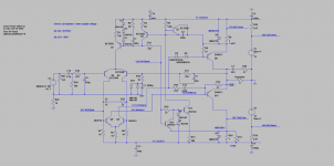
Elvee, could you please have a look at my Pmos circlo sim
in post #456? Does it look right, more or less?
in post #456? Does it look right, more or less?
Sorry!I only see .asc files in your zip, and no models
Attached here.
Attachments
It does not work properly: the Circlo engine runs out of steam, probably because of the high supply voltage and the poor lambda of the PMOS.Sorry!
Attached here.
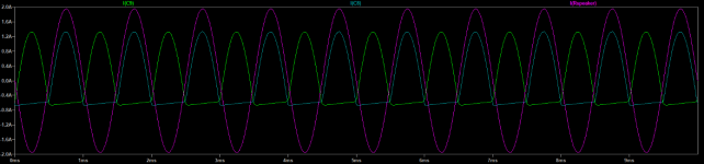
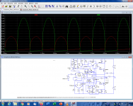
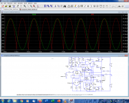
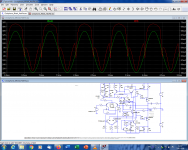
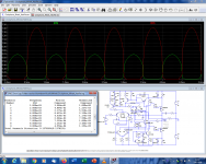
Here are the currents in the sensing resistors: you can see clearly that the engine loses control and that the quiescent current falls to zero, with a disastrous effect on the THD:
The tail current of the VAS also has a nasty look:
If the values of R7/R14 are doubled, things return to normal:
An unexplained asymmetry remains between the two quiescent currents, but it looks mostly harmless
A cap subjected to pure DC cannot heat up. To do that, an AC current is required, and since a cap has a Dissipation Factor, part of the apparent power will be converted to heat.Hi Elvee,
Can you please explain the currents in post #461 ?
A current applied to the impedance of a cap will generate a voltage, because of the generalized Ohm's law, and this voltage has to be visible.
For example, if you use a too small filter cap in a supply, say 470µF for 3A, it will be subjected to a huge ripple, will see a large 100Hz voltage and will heat up and explode very quickly.
If your circlophone sits idle, the ripple current will be minimal, and practically no AC current will be present
Attachments
Last edited:
Hi Elvee,
First, thanks for the wonderful amps. They are working great. My preference is the BJT version with D1047 outputs.
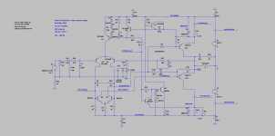
I was wondering if a lower PS voltage version (like your "bonsai" version) would work with just a PNP output transistor. I am considering B817 with HFE around 120 - 140 for this circuit. If you get the time, can you please review the circuit.
I am considering this variant for the hot summer months, and till I get bigger sized heatsinks.
Thanks
First, thanks for the wonderful amps. They are working great. My preference is the BJT version with D1047 outputs.
I was wondering if a lower PS voltage version (like your "bonsai" version) would work with just a PNP output transistor. I am considering B817 with HFE around 120 - 140 for this circuit. If you get the time, can you please review the circuit.
I am considering this variant for the hot summer months, and till I get bigger sized heatsinks.
Thanks
Attachments
A +/-17V supply is still within the range of the regular C, so changing the sexes of all transistors like you did for use with PNP transistors is sufficient.
You can adopt the Circlobonsai minimization to reduce the heat dissipation if you like.
Here is a link to that variant:
♫♪ My little cheap Circlophone© ♫♪
You can adopt the Circlobonsai minimization to reduce the heat dissipation if you like.
Here is a link to that variant:
♫♪ My little cheap Circlophone© ♫♪
Excellent news, even if they come as no surprise: the C topology has been twisted, sex-changed, upgraded, simplified and adapted in many ways, yet it has never failed to the deliver the goods.Hi Elvee,
Both channels of the lower voltage circlophone bonsais are singing.
It is an ugly little duckling, but it performs remarkably well.
It would be even better if the topology was elegant, but we can live with something that is just plain and effective
I have tried to modify the layout designed by Mr project16 considering omission of possible Earth loops in the layout and accommodation of TO3 transistors. Board size is 80x117 mm. I would request interested Boarders to please check this layout for errors and suggestions for further modifications.
Attachments
I have tried to modify the layout designed by Mr project16 considering omission of possible Earth loops in the layout and accommodation of TO3 transistors. Board size is 80x117 mm. I would request interested Boarders to please check this layout for errors and suggestions for further modifications.
1) Clean ground and dirty ground are mixed up together.
All dirty ground traces (as these that go to big electrolytics) should go directly to main ground connector, NOT to the input connector.
Input ground should only go to input resistors, capacitors, and to the feedback RC connected to the base of Q3.
Everything else is dirty ground.
To avoid ground loops and hum, I usually keep dirty ground and clean ground totally separated on the PCB, and then have 2 wires from common ground from PSU, to the PCB.
2) Trace leading from OUT to the feedback loop going to the base of
Q3, should be taken from the actual OUT connector,
NOT from one of the output transistors.

- Home
- Amplifiers
- Solid State
- Building Elvee's Circlophone: Documentation, Parts, Accessories, & beginner friendly