MN2488 maximum power dissipation is 3/4ths as much as MJL21194.
Max transformer with 8 ohm speaker 25+25vac although somebody might try a low-VA 28+28vac transformer.
That amplifier can use BC550C input for high quality.
Max transformer with 8 ohm speaker 25+25vac although somebody might try a low-VA 28+28vac transformer.
That amplifier can use BC550C input for high quality.
BC141-16
Hi all!
I found some BC141-16 and I think they may be suitable for Q5 and Q6 (instead of 2N3019), what do you think?
http://www.datasheetcatalog.org/datasheet/stmicroelectronics/9291.pdf
Thank you and friendly!
Hi all!
I found some BC141-16 and I think they may be suitable for Q5 and Q6 (instead of 2N3019), what do you think?
http://www.datasheetcatalog.org/datasheet/stmicroelectronics/9291.pdf
Thank you and friendly!
If they are typical (which is likely), they will be suitable, otherwise the Ft would be a bit low, and the collector capacitance a little too largeI found some BC141-16 and I think they may be suitable for Q5 and Q6 (instead of 2N3019), what do you think?
Thank you for that answer Elvee.
I will then take 2N5551 as mentioned by danielwritesbac
Regards!
I will then take 2N5551 as mentioned by danielwritesbac
Regards!
Do please notice that all normal size builds use Heatsinks at VAS, Q5, Q6 and please do use a transistor big enough for appropriate power dissipation tolerances for your build. The big TO220 size 2SC5171 is conveniently big enough that you won't need to heatsink it at Q5, Q6.
The 2N5551 was not promoted for Vas/Inverter area, Q5, Q6.
Actually, the 2N5551 was promoted for Sensor area, Q12, Q13.
It only took a year to write Post1 of this thread. Here's an excerpt:I will then take 2N5551 as mentioned by danielwritesbac Regards!
The 2N5551 was not promoted for Vas/Inverter area, Q5, Q6.
Actually, the 2N5551 was promoted for Sensor area, Q12, Q13.
Last edited:
Danielwritesbac thank you!
I realized my mistake after reading but can no delete my post.
Regards!
I realized my mistake after reading but can no delete my post.
Regards!
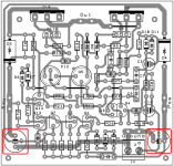
I modified my Darlington PCB layout for a possible higher wattage build.
* All transistors are Japanese type
Any opinion are welcome.
Terranigma,
Is this lay-out final? I think I will go for this one, japanese devices dominates the industry here in PH. They come cheap and always in availability. Will you be sharing the bottom copper lay-out?
Thanks!
I didn't know if it was a mistake Or if you were making a miniaturized Circlophone for use on the computer desk.Danielwritesbac thank you! I realized my mistake after reading but can no delete my post. Regards!
Miniaturized Darlington version would be especially convenient and could be SMD if you wanted to.
Terranigma,
Is this lay-out final? I think I will go for this one, japanese devices dominates the industry here in PH. They come cheap and always in availability. Will you be sharing the bottom copper lay-out?
Thanks!
I'm thinking about altering final layouts :
* BC/2N type small transistors (zener and zenerless)
* Japanese small transistors (zener and zenerless)
Total 4 different layouts. Each layout can be used by inverting polarity and device type at each side, thus 8 different implementation according to builder preference. If we count mosfet and darlington output versions separately, then 16 different implementations in total.
For Japanese + zener option, my previously posted layout seems finalized, should be applicable at least. I will send you pcb print file for it.
I just figured it out we can use a single layout for zener or zenerless builds if transistor is going to be base-to-ground. I'm working on layout.
Hero!I just figured it out we can use a single layout for zener or zenerless builds if transistor is going to be base-to-ground. I'm working on layout.
Hi everyone!
I still change my circuit design but I have a little doubt tracks two tracks that pass between the two capacitors, any suggestion is welcome.
For Schottky diodes (D4 and D5) I have SB560 (60v - 5A).
http://www.vishay.com/docs/88721/88721.pdf
It is ok?
Regards!
I still change my circuit design but I have a little doubt tracks two tracks that pass between the two capacitors, any suggestion is welcome.
For Schottky diodes (D4 and D5) I have SB560 (60v - 5A).
http://www.vishay.com/docs/88721/88721.pdf
It is ok?
Regards!
Attachments
Hi everyone!
I still change my circuit design but I have a little doubt tracks two tracks that pass between the two capacitors, any suggestion is welcome.
Did you check the whole circuit? R22 seems an extra resistor that doesn't exist on original circuit.
Last edited:
Did you check the whole circuit? R22 seems an extra resistor that doesn't exist on original circuit.
I added R22 to possibly get two 2ohms 1/4w resistors (R8 => 1ohms - 1/2w) but I will certainly remove it to remain in the original scheme.
Regards!
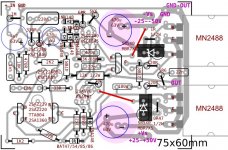
Layout updates
Changes :
* It is now Transistor/Zener option on same layout
* Some resistors laid down at input stage
* R21 pads thickened due to possible two pin CCS small module card insertion
Note: 25-50V per rail voltage range is a theoretical estimation.
Changes :
* It is now Transistor/Zener option on same layout
* Some resistors laid down at input stage
* R21 pads thickened due to possible two pin CCS small module card insertion
Note: 25-50V per rail voltage range is a theoretical estimation.
Attachments
Last edited:
A choice. Nice! Good features there.
Just a note:
Darlington 25~35v or FET 25~50v
It seems like plans and high voltage parts for FET are getting into the Darlington board. I don't know. Does the one board do both?
Just a note:
Darlington 25~35v or FET 25~50v
It seems like plans and high voltage parts for FET are getting into the Darlington board. I don't know. Does the one board do both?
A choice. Nice! Good features there.
Just a note:
Darlington 25~35v or FET 25~50v
It seems like plans and high voltage parts for FET are getting into the Darlington board. I don't know. Does the one board do both?
In this board minimum Vce spec'ed part is at 120V. So, I didn't bother to show 50V there. It is going to be the same as mosfet version - except 120R's and output stage of course.
I haven't arranged a BC/2N version of PCB yet. In this case, supply margin will be limited by BC5X0C's at max 38-40V.
I don't want to limit the builders. I just want to prepare a template for different possibilities and requirements. BC/2N version should be applicable for mosfet version too. Hope you get my idea.
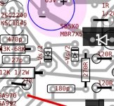
I arranged 180pf/270R comp network for transistor version and I didn't altered for zener version as shown in original schematic. Simulation doesn't show any difference with this setup. Should I re-arrange the comp. for zeners (270R to the other side of zeners) as shown in original schematic? It is very easy. Elvee?
Last edited:
It is completely equivalent: the zeners dynamic resistance when they conduct connects the two nodes in ACI arranged 180pf/270R comp network for transistor version and I didn't altered for zener version as shown in original schematic. Simulation doesn't show any difference with this setup. Should I re-arrange the comp. for zeners (270R to the other side of zeners) as shown in original schematic? It is very easy. Elvee?
[Posted to main thread]
Given the 30+30vdc (60v) operating voltage and unregulated power (surges happen) we might need to list something other than BC556B (maxed at 60V) in the sensor area.
Sorry for late correction but, BC5X6 series specified with -+65V max Vce.
BTW, PCB layout versions seem ready and I'm a bit uncertain about how to introduce them within a clear and understandable way.
* There is going to be physically different 2 versions: BC-2N small transistor type and Japanese small transistor type
* Each pcb can be applicable for Darlington and Mosfet output preference
* Each pcb can be applicable for Zener or Zenerless (+Extra Servo transistor) preference
* Output devices can be N(PN) or P(NP) type
* Remaining active parts and supply polarity must have adapted according to output device type and Sensor/VAS device preference
So, instead of showing a specific transistor type on layout, I think we must categorize each section and provide a list of suitable devices for each section
For example:
PNP Servo(VAS) : Philips,Harris BD140 (Vs<=37V), TTA004,....
NPN Servo(VAS) : Philips,Harris BD139 (Vs<=37V), 2SC5171-FLIPPED,...
PNP IN (BC/2N): BC560C (Vs<=40V),...
NPN IN (BC/2N):
PNP Input (Japanese): 2SA970-BL, 2SA992,...
NPN Input (Japanese):
and goes on...
Last edited:
- Home
- Amplifiers
- Solid State
- Building Elvee's Circlophone: Documentation, Parts, Accessories, & beginner friendly