Hi guys, as tittle said "Building BA-3 as analog output stage of noDac", well the noDac outputs 0,19Vrms so I was looking for something with a gain x10 to get near the standard 2Vrms, helping me to take the BA-3 option because I own original SK170BL, SJ74BL, K2013 & J313 from when I used Erno Borbely stuff, also it's not complicated to do it and adjust (very similar to Borbely), don't take to much room inside noDac box and is a lot of more easy and a lot of less money than make a DHT 4P1L with the same gain of course I don't expect the same SQ.
I read with attention NP BA-3 article, it seems with standard resistors values BA-3 fits nicely the x10 gain I'm looking for.
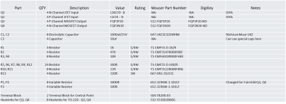
Attached NP BA-3 article to know if it's the latest or there is other new and also B.O.M. for a balanced unit that I will not do because all my system is SE.
I read Jfets have to be "matched if possible" at 10mA Idss, I have on hand:
SK170BL
9.48mA x 2
SJ74BL
9.02mA x 1
9.03mA x 1
or
10.11mA x 1
10.24mA x 1
What's best pair to use with the SK170BL?
I guess with these values P1 & P2 will remain 500R, right?
With the input voltage of +-25V can reach the x10 gain?
I will post pics of my work in progress.
TIA
Felipe
N.B. Big thanks to Jim aka 6L6 to give me a couple of PCB.
I read with attention NP BA-3 article, it seems with standard resistors values BA-3 fits nicely the x10 gain I'm looking for.
Attached NP BA-3 article to know if it's the latest or there is other new and also B.O.M. for a balanced unit that I will not do because all my system is SE.
I read Jfets have to be "matched if possible" at 10mA Idss, I have on hand:
SK170BL
9.48mA x 2
SJ74BL
9.02mA x 1
9.03mA x 1
or
10.11mA x 1
10.24mA x 1
What's best pair to use with the SK170BL?
I guess with these values P1 & P2 will remain 500R, right?
With the input voltage of +-25V can reach the x10 gain?
I will post pics of my work in progress.
TIA
Felipe
N.B. Big thanks to Jim aka 6L6 to give me a couple of PCB.
Attachments

You will be shocked at how good the BA-3 sounds. Might even replace the DHT stage.make a DHT 4P1L with the same gain of course I don't expect the same SQ.
They’re all a little away from the 2sk170, but P3 should help improve the match. You probably want some H2 anyway, so a little mismatch is okay.What's best pair to use with the SK170BL?
Yes, but going with 1k will give a little flexibility.I guess with these values P1 & P2 will remain 500R, right?
And yes, with +-25V, you can get 10X gain 0.19 Vrms input.
Have fun!
Thank you ra7.
So I will choose:
SK170BL
9.48mA x 2
SJ74BL
9.02mA x 1
9.03mA x 1
And use 1K pots for P1 & P2.
So I will choose:
SK170BL
9.48mA x 2
SJ74BL
9.02mA x 1
9.03mA x 1
And use 1K pots for P1 & P2.
Q3 is the P-channel device, so that would be the J313.
In the article, the bias is set to 50 mA for the output stage and approximately 8-10 mA for the input stage. I'd guess 60 mA is the total bias current.
In the article, the bias is set to 50 mA for the output stage and approximately 8-10 mA for the input stage. I'd guess 60 mA is the total bias current.
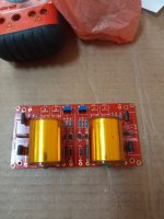
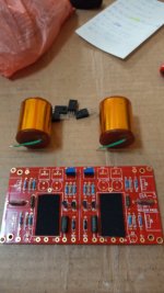
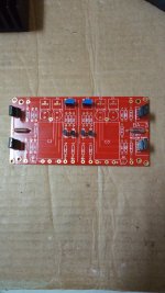
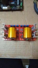
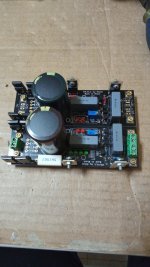
Thanks Ra7. I have to make a new order to Mouser because the electrolytics that I have are 50-63V so bigger diameter than PCB allows, four 1K trimmer and four heatsinks that also don't have in my stash. Attached pics with work in progress.
Attachments
Last edited:
Nice! Once you have the parts it can come together in an afternoon.
10 uF is plenty big. You can check the -3db point with the high pass filter calculator here:
https://www.digikey.com/en/resource...sion-calculator-low-pass-and-high-pass-filter
The R is the input impedance of the following stage. 10k is a good low value. Most things will have higher than 10k input impedance.
The 801A preamp have an input impedance of 150K so 0.53uF will be enough for 20Hz, I have on hand a couple of nice Auricaps 1uF 600V.
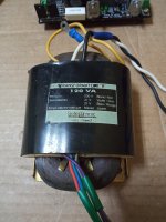
I have to decide what regulators I will use, I have on hand one +- regulator Salas BiB SSLV1.1 and a nice R-Core with dual secondary 21A 120VA so 60VA each secondary, the regs. have rectification & mains reservoir capacitor so be good to save space.
I have to decide what regulators I will use, I have on hand one +- regulator Salas BiB SSLV1.1 and a nice R-Core with dual secondary 21A 120VA so 60VA each secondary, the regs. have rectification & mains reservoir capacitor so be good to save space.
Last edited:
Listening the BA-3, could I bypass the 1K input resistor, I ask because the Vin it's too low circa 0,19Vrms so the resistor take off a lot of sound?
Some music sound weak and far.
1st stage Jfet only reach 6mA.
Some music sound weak and far.
1st stage Jfet only reach 6mA.
Last edited:
Also some music is masked and not heard or heard too little or blurred.
Let's see if it will sound better after the 3-4 hours of burning.
Let's see if it will sound better after the 3-4 hours of burning.
Removing the 1k won’t do anything.Can you describe what’s generating the 0.19Vrms? The stage before the Ba-3? You can measure at the 1k resistor and see if are getting any AC signal at the JFET inputs.
The difference is 8 mVrms, using SG 1KHz sinuswave.
Why when connect the SG 1KHz sinuswave with 0,190Vrms when connect to BA-3 lower the voltage to 0,009Vrms?
Seems BA-3 works ok, with 0,009Vrms gives 0,090Vrms.
Why when connect the SG 1KHz sinuswave with 0,190Vrms when connect to BA-3 lower the voltage to 0,009Vrms?
Seems BA-3 works ok, with 0,009Vrms gives 0,090Vrms.
Last edited:
Check and confirm the R2 is 47Kohm.
Do you have any DC offset (DC voltage) at the junction of R1 and R2?
Is the JFET's current close to 8ma?
Are P1 and P2 shrting the C1 and C2 caps? I.e. what are the P1 and P2 wiper positions? Middle?
Do you have any DC offset (DC voltage) at the junction of R1 and R2?
Is the JFET's current close to 8ma?
Are P1 and P2 shrting the C1 and C2 caps? I.e. what are the P1 and P2 wiper positions? Middle?
- Home
- Amplifiers
- Pass Labs
- Building BA-3 as analog output stage of noDAC