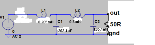
The noDac it's an USB I2S output filtered with a 4th LPF, attached schematic, there isn't the output coupling capacitor that the value depend of input impedance that for BA-3 47K is 1,69uF but I installed 4,7uF that's the value that I have on hand..
There isn't schematic it's only a low pass filter like posted before, I use Amanero for USB-I2S so output pins:
Pin number 3, I2S DATA/DSD1, Out, Data stream LVCMOS 3.3V 47ohm, channel LEFT
Pin number 5, I2S FSCLK/DSD2 Out, Frame sync LVCMOS 3.3V 47ohm, channel RIGHT
The noDac it's only for DSD, so you only can listen DSD music and have a player that converts all PCM files to DSD files.
Attached an image with other LPF for reference and my filter without output coupling capacitor that value will depend of load (pic don't show the cap because I was using a step-up after the LPF).
Enjoy and welcome to DSD paradise.
N.B. I also dislike flip flops because kill the music so I accept to listen a residual noise like when you play vinyl.
Attachments
Last edited:

I’m not sure of the exact value, but it would be equal to or less than R13 at 332R.
I use HQPlayer, so can output DSD. This might be an interesting experiment, though I worry a little about damaging the JLSounds board.
I use HQPlayer, so can output DSD. This might be an interesting experiment, though I worry a little about damaging the JLSounds board.
I guess is higher because my Intact Audio AVC doesn't sound as good as with low impedances.
In place of AVC I tried with a passive attenuator ladder configuration 100K Dale RN resistors with Elma switch and improved a lot the sound quality.
In place of AVC I tried with a passive attenuator ladder configuration 100K Dale RN resistors with Elma switch and improved a lot the sound quality.
I am considering building a BA-3 to use as a preamp (eventually with an F4). I am trying to design a stepped attenuator to place at the output of the BA-3. (I am given to understand that sonically it is better to have the attenuator after the preamp, assuming my sources (a cd player and a phono preamp) do not cause over-modulation in the preamp.) I know that the input impedance of the F4 is 47k, but I need to know the output impedance of the BA-3 front end to make the calculations.
Anybody can help?
Thanks.
Anybody can help?
Thanks.
The link one person said 1K2 and the other 5K so still no clear, but sounds more in agreement with my experience with the AVC.
I think if you put a buffers before preamp, then any impedance will have no issue
Thanks, yes I know, but I'm a believer that 99% of times less is more.
Using 1kHz SG with 100K as load
Output impedance 5K8
Damping factor 18.23
Using 1kHz SG with 100K as load
Output impedance 5K8
Damping factor 18.23
Last edited:
- Home
- Amplifiers
- Pass Labs
- Building BA-3 as analog output stage of noDAC