A little progress, finally. Ordering a couple new toroids from Antek, then I need to pick a chassis...


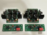
Build is basically done!
I first used the amp at 250mv across r17 as written here:
0.8 A 160 - 170 mV
1 A 250 - 270 mV
1.2 A 340 – 360 mV
Later I tried cranking up the bias current to see how it would sound, but one of the channels wont flow more than 254mv across r17, while the other will go above. Any ideas what could be causing this, or where I should look around to diagnose?
It's a wild sounding amp. I've never gotten so much detail out of music.
Very nice build. 🙂
Max. Bias current depends on R10 and J113 Idss, which varies. Seems that you got one J113 that needs lower resistor. You could change R10 to 47R or add 100R in parallel.
Exactly that. And with adequate loudspeakers, sound stage is equally incredible.It's a wild sounding amp. I've never gotten so much detail out of music.
Max. Bias current depends on R10 and J113 Idss, which varies. Seems that you got one J113 that needs lower resistor. You could change R10 to 47R or add 100R in parallel.
Thank you!Lookin’ good IAIMH!
Which Antek’s did you order?
I ordered a couple 2215s.
Super excited to see more builds popping up! I've been waiting on this one for a while. I had to tear myself away from the bench this morning to actually go outside. The horrors!!!!

Nice and simple amp.
I was curious how Microcap matches other simulation programs...
Also to see if it results in unrealistic low THD values, what it obviously does not.
...and how different amps compare to my own stuff in simulation.
I had to increase the 2.7k to get the desired 1A bias. Maybe some bad model.
What is the diode for?
THD: 1Wp -121dB, 10Wp -110dB
Different opamps did not change anything.
Thanks. And it sounds very nice too. 🙂Nice and simple amp.
Regarding simulation, LTSpice was calculating only 6 dB lower distortion than measured. Your numbers are almost the same as I got with LTSpice.I was curious how Microcap matches other simulation programs...
Also to see if it results in unrealistic low THD values, what it obviously does not.
...and how different amps compare to my own stuff in simulation.
It is likely J113 model issue. R11 shouldn’t affect bias. Try with R11 = 2K7 and reduce R10/RV1.I had to increase the 2.7k to get the desired 1A bias. Maybe some bad model.
Diode is used to account for 0.6 V higher Vgs of P MOSFET, compared to N part.What is the diode for?
True, not much at 1 kHz distortion, but they would for slew rate and overall stability, especially with capacitive loads.Different opamps did not change anything.
Ok, understand, however with diode I get 385mV offset on the opamp output, without diode it is only 23mV.Diode is used to account for 0.6 V higher Vgs of P MOSFET, compared to N part.
Likely models problem again. In practice and with LTSpice simulation, offset at the opamp output is about 50 mV. I use Ian Hegglun & keantoken models for laterals.
Shorted diode was responsible for low bias as 0.6V was missing.
Shorted diode was responsible for low bias as 0.6V was missing.
Output stage alone was tested and listened to in the first development phase. It works very well and higher supply voltages can be used. Distortion is low and harmonics profile is monotonic. However, damping factor is in the low range (didn’t actually measure for the OS alone).
So, yes, output stage can be used with other frontends.
So, yes, output stage can be used with other frontends.
tombo56, I couldn't have expected a better reply. It is just what I need. I use FostexFE168Sigma speakers in ML-TQWT enclosures. They need amps with higher output impedances. And I love to listen to amps and preamps with zero NFB because of their natural sound and the way the sound envelope grows when the music hits crescendos. Thank you very much.
A little more progress. Prasi's 4320 boards + R21 all tested and working well.
Need to pick a chassis and get the output devices mounted.
@tombo56 - Legend!
Need to pick a chassis and get the output devices mounted.
@tombo56 - Legend!
Attachments
I scoured my local area for a brick and mortar store that had an M3 tap set on hand... so... Bezos' bookstore will deliver tomorrow.
PSU in the chassis... layout pretty much final and "inspired" by the origin build.
PSU retested in the chassis with the dim bulb / variable transformer and all other safety nets removed. All good.
Pretty lights...
Drill and tap 4 holes tomorrow or Sunday... and if all goes to plan... music!
For those that like pics...
Right now, the R21s have ~2V5 drop unloaded (22V0 prior set to 19V5 after). I'll adjust as necessary when I add an amp-sized load. Hopefully they'll drop into that sweet spot of ~1V5 drop.
- Home
- Amplifiers
- Solid State
- Building an ultimate low power class A amplifier – my way