It does its got a few volts across it and is dissipating a watt or two. Is got all the cathode current flowing through it. I guess in those days big trimmers were common.
no.... such a wiper intended to dc balance the two outputs tubes.... this does not happen, with this design....
The grids have a few volts on them (e.g. 7.5V if cathode current 50 mA per tube and the pot was in the middle). The pot changes the grid voltage balance and hence the output tube DC balance.
The grids have a few volts on them (e.g. 7.5V if cathode current 50 mA per tube and the pot was in the middle). The pot changes the grid voltage balance and hence the output tube DC balance.
No. grid resistors are 100k , and very hard to make out ; the wiper is 800 ohm? ?? ?? ..... just not seeing it. besides even KOC has better dc balance circuit than this.
.... and this voted one of five best amplifiers in 2020 ?
Well, I am laying out Surface 4, now as we speak, to go head-to-head against this one. Will not only be a para-feed drive, but will do something few para-feed amps can do, that is to deliver a full 18 watts rms SE, [two EL-34 power tubes per channel] out to the output transformer. . . .. . and because is a para-feed, we can run with a much smaller O/T rather than these 11 pound air-gapped and potted O/T's that cost a small fortune on a BOM.
Last edited:
mooreamps, the schematic in post #14 is not the actual schematic being used - so no point at all in assessing that schematic in this thread, or your own amp as a comparison.
The schematic in post #14 is the Heathkit W4M - if you want to read up on that vintage amp then link is below.
http://www.mcmlv.org/Archive/HiFi/HeathkitW5M.pdf
The original Williamson used that balancing method plus an additional pot for common bias level setting - you can read up on the original Williamson in this link:
https://www.dalmura.com.au/static/Williamson%201952%20The%20Williamson%20Amplifier.pdf

The woodwork will be oak, the chassis 3mm aluminum.
As stated in the original post, the OPTs are Hammonds.
As stated in the original post, the OPTs are Hammonds.
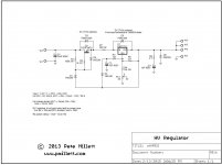
Maida Style Regulator
This is the Maida Style Regulator that I am planning on using.
I don't yet know what my B+ requirement will be so I will need to play with the value of R4.
I'm puzzled as to why this is specified as a 2W component in the illustrated configuration ?
Iadj of the LM317 is 100uA (max).
In the illustration R4 is 13K.
100uA x 100uA x 13K = 1.3e-4 Watts
If I reverse the designer's calculations R14 would have some 12.5mA flowing through it in order to necessitate a 2W component.
I'm going to need R4 = approx 40K.
This adds the question about the rating of RV1 ?
Attachments
Last edited:
I think I've answered my own question.
The current through R4 and RV1 is set by the value of R5.
With R5 at 121R this equals approx 10mA.
10mA through 13K is approx 1.5W hence the 2W component.
10mA through RV1 is approx 250mW.
How low can R5 go ?
The current through R4 and RV1 is set by the value of R5.
With R5 at 121R this equals approx 10mA.
10mA through 13K is approx 1.5W hence the 2W component.
10mA through RV1 is approx 250mW.
How low can R5 go ?
The illustrated circuit is configured for 155V output.
I've figured out how to get that up to 400V.
Will R1 need adjusting ? I reckon it might need to be reduced to about 36K.
I'm not sure what the Vin of this circuit is, let's assume 400V from C1.
R1 sets the bias current for D1. In the illustration. Vin(400V) - Vout(155V) - Vd1(15V). 100K relates to approx 2.3mA. In order to maintain 2.3mA with Vin at 500V and Vout at 400V R1 would need to be 36K.
My Vin is approx 500V so C1 is increased to 22uF / 500V.
I couldn't get FQPF2N70 so I've got FQPF2N80. The only difference in this application is Vds is 800V.
Last edited:
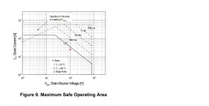
Beware that the SOA of that FET intersects at 200mA at 200V or so, now for switching mosfets like these you have to take those specifications with a barrel/wheelbarrow of Salt due to secondary breakdown concerns if you put DC through them. There is an appnote on that.
On a bad day and high line you may have 550V unfiltered B+ and thus about 120-130V over the mosfet, Will it survive this? I dont know, that depends on how well you cool it.
There are specialist mosfets on the market that have vastly increased Safe operating area.
I can highly reccomend these, if the mosfet goes, it shorts out and takes out the 317 as well.
IXTP15N50L2 IXYS - Transistor: N-MOSFET | unipolar; 500V; 15A; 300W; TO220-3; 570ns | TME - Electronic components
Your correct in assuming 36K will work just fine. But you need to make sure that this current plus about 5mA flows through the output divider on the 317, otherwise it will go unstable under no-load conditions. Which could cause device failure.
Cheers,
V4LVE.
If that circuit is not to your liking then I have used this before. Q2 needs to be high voltage, and M1 a FET with appropriate ratings. Q3 is a current limit.

I'd be worried about using a 500V device in a circuit that, under fault conditions, could see 550V

The FQPF2N80 should be OK at Vin 500V, Vout 400V and Iout 250mA as long as I keep it cool.
I might try adding a series resistor at the input to give it a helping hand.
200R at 250mA will drop the input voltage by 50V. (This will all depend on what my final B+ needs to be)
I might try adding a series resistor at the input to give it a helping hand.
200R at 250mA will drop the input voltage by 50V. (This will all depend on what my final B+ needs to be)
Attachments
Last edited:
The problem is those SOA curves for switching type mosfets are often a lie. Almost all mosfets have some degree of second breakdown type behavior, and only *some* data sheet curves show it. Newer low Qg types are far worse about it than older, lower speed, lower voltage types like the IPRP240. To minimize your problems with the newer types, use devices with a moderate current rating and a high Rds(on). You don’t need . 02 ohm Rds(on) for a tube voltage regulator. Upwards of an ohm is fine. They will handle a larger portion of their power ratings at high voltages compared to the “best switch you can get” type.
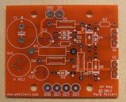
Well the PCB has arrived
The PCB and its schematic have finally arrived.
Surprise No.1 is that it is fully populated.
Non-surprise No. 2 is that what meagre instructions that are supplied are in Chinese.
Looking at the schematics I'm assuming that B+ should be 450V as that is what you would get by rectifying 320VAC.
There are no instructions as to how to set up the biasing of the amplifier ?
Attachments
C12 and C9 are only 450V caps? No headroom to a 450V B+. I’d use the tap on the power trafo that gets you closest to 450V without going over (“the price is right” tap).
As far as where to set the bias, keep it under 25 watts per output tube. There will be some minimum you need to keep distortion low - probably 15 to 20 mA. More may sound better, and the value you like will depend on the trafo’s primary impedance. The EL34 data sheet gives suggested bias for multiple load and supply voltage ranges which are known to work well. Ultimately you are limited by the 25 watt dissipation limit. Start out as negative as g1 will go, and adjust up. Adjust push pull pairs up symmetrically a bit at a time to avoid putting a large DC offset in the output transformer. You don’t want to magnetize it.
If you don’t know what the OPT primary impedance is, feed 6.3VAC into the secondary and back calculate it. It’s probably one of the common values (6.6k, 5k, 3.8k, etc).
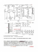
Welcome to the most complete do it yourself guide on the D. T. N. Williamson tube amplifier., chapter 10 Putting into Operation and Adjusting Bias
This similar design is biased at 62mA / tube.
That same similar design has B+ at 435V.
This similar design is biased at 62mA / tube.
That same similar design has B+ at 435V.
Last edited:
- Home
- Amplifiers
- Tubes / Valves
- Building a Williamson EL34 amplifier