I was using the TIP122 a "REAL" darlington but the results were exactly the same.
For some reason or other the BC550C isn't acting as I would expect it to. Its perfectly OK and has been swapped with a new one.
I'm not familiar with the maths of working out how the BC550C should act in this configuration. If I were to swap it with a virtual zener, what voltage should the zener be ?
I'm not suggesting that I will substitute a zener, I am just trying to appreciate what is happening in this circuit. Or NOT in my case.
did you use the right value cap? In delay circuits usually a cap charges, fires a transistor which turns another one in in a way that it stays on and in firing the second it allows electricity to the relay. Google 'latching circuit.'
So value of cap is critical.
So value of cap is critical.
I'm having a bid of a headache with the delay section.
How much of a delay should this circuit provide ?
For some reason or other the base of my Relay Driver isn't reaching ON for about 10 minutes. If I omit the BC550 I get virtually no delay. I can work around the problem if I could figure out how long the relay should be de-energised for.
The junction of the timing R & C are rising to 12V as I would expect. The issue seems to be the use of the BC550C as a Zener to de-sensitise the relay driver.
I'm not using the BC517 I'm using 2 x BC550Cs connected as a darlington.
Are you running stock values?should be about 10 seconds.
I've just "Bitten the Bullet" and ordered a pile of BC517s just to see if that works.
Unfortunately I made the PCB to accept the TIP122 so I'll have to bend the legs around a bit.
The HM 2xBC550C should equate to to the BC517 though.
Everything else is STOCK.
Unfortunately I made the PCB to accept the TIP122 so I'll have to bend the legs around a bit.
The HM 2xBC550C should equate to to the BC517 though.
Everything else is STOCK.
How ODD.
I've replaced the BC550c with two 1N4148s in series (ie a 1.4V zener) and used the TIP122 as the relay driver and it works perfectly.
It just didn't work with the BC550c acting as a zener.
There's nothing wrong with the BC550c's that I was using, they both test correct.
I've replaced the BC550c with two 1N4148s in series (ie a 1.4V zener) and used the TIP122 as the relay driver and it works perfectly.
It just didn't work with the BC550c acting as a zener.
There's nothing wrong with the BC550c's that I was using, they both test correct.
Odd thing though.
Measuring the Base drive voltage of the TIP122 with the BC550c using a DMM caused the relay to oscillate.
Nothing made sense. It's perfectly OK with the 2 x 1N4148.
I'm just wondering if it might be a bit quick though. the relay operates after just less than 2 seconds.
Measuring the Base drive voltage of the TIP122 with the BC550c using a DMM caused the relay to oscillate.
Nothing made sense. It's perfectly OK with the 2 x 1N4148.
I'm just wondering if it might be a bit quick though. the relay operates after just less than 2 seconds.
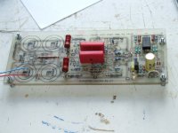
The TIP122 for the relay drive is under the board as it didnt quite squeeze past the timing cap on the top of the board.
You have a greater Vbe drop vs that of the BJT, i think, and this is reducing turn on time. I believe a larger cap will slow it down. 220uF. I could be wrong.
The BC550 zener effect as used in the original scheme lies higher at about 6.3V. For variations of lower threshold the time capacitor's value has to grow accordingly, but 2 secs are enough to avoid power up thump on audio outputs.
Since you established a working variation and the relay clicks alright you are ready to go. Time delay is up to you. Just look to have no audible power on thump and a rapid power off relay release.
Spooky hum problem
Hi all,
i have a funny problem with my DCB1.
Since i have finished my F5 on sunday, i have disconnected my 300B mono's and now the F5 runs with the DCB1.
Now the following happened:
If i connect only the right channel from the DCB1 to the F5, all is dead silent.
When the left channel followed i have a hum on both channels.
If i disconnect the right channel, the hum stays on the left channel.
All that is intependend to the connected inputs and the mains cable...😡
Yes, if i disconnect everything including the mains, the problem stays!
Very crazy... Perhaps someone has a good idea...😱
Oscillation? Do you use same long cables as it was for the 300B amps?
Hi Salas,
Yes, the same cables. I have tried some other Nordost Tyr i have with the same result.
BTW, it's a deep hum but not loud...
Last edited:
- Home
- Amplifiers
- Pass Labs
- Building a symmetrical PSU B1 buffer