I bought a batch of 100 from spencer and they ranged from about 6.5 t0 11. 2.2 is definitely very suspect.
Andrew, when did you start using 1R0? Isn't that a tad low? I used a 0.1% 100 ohm resistor and that seems to work quite nicely. Perhaps 100 ohms doesn't give quite enough resolution though for really close matching, a 10 ohm resistor would allow me to use the 200mV range on the multimeter rather than the 2V range... I assume this is the reason for going with such a low resistor value? Or is it because you can just use the reading without needing to divide by the resistance?
Tony.
I agree.
You do need at least 10R0 to get full resolution on most meters.
My initial measurements were taken with only the shunt of the meter as a load.
My original SwapMeet post for 0-15 0-15 Toroidal has been amended. Apparently, these rescued transformers are 60VA and not 50VA as originally suspected.
THere are different grades of fets. If you were sold BL fets, that is low. EVen if you were sld GR grade, I think that is still low.
For those that can use them: I just found a bag with a quantity of original 2SK170. I used them for finding matched pairs for 3 pieces DCB1 and they were left. make me an offer if you want them. Their Idss range from 7.XX to 10.xx mA.
Before I go tearing into my supplier.
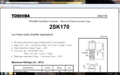
I've just been looking at the datasheet for the 2SK170.
The parameters are quoted at Vds=10V Vgs=0V and Idss=3mA.
That's not too far from what I am seeing.
That is about minimum transconductance expected. 22 milliSiemens is the low side GR(een) grade's bottom Yfs. Anything marked BL(ue) shall vary between 6-12mA IDSS @ 10V VDS with a midway Yfs of 37mS. Else its a bad or fake sample.
Dalbani are being helpful. They are just as stunned as we are that they are being conned.
Check IDSS with this direct method again: http://www.diamondstar.de/transistor_matching_jfet.html
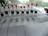
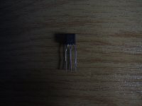
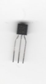
Show us a good macro picture of the JFETS there:
http://www.diyaudio.com/forums/parts/82638-my-transistors-original-copy-44.html
Little Buggers are not easy to photograph.
I've tried my best - see what you think.
They definitely look "brushed" to me. That would be my first clue that they have been remarked.
I've tried my best - see what you think.
They definitely look "brushed" to me. That would be my first clue that they have been remarked.
Attachments
Last edited:
Let's hope that Dalbani will try to honour his reputation.
Can NO suppler be trusted these days ?
Can NO suppler be trusted these days ?
Are the 2SK170s still in production or are our favourite suppliers having to buy from wherever they can get stock ?
I can get supposedly genuine 2SK170GRs.
Must be better than the fakes that I've received.
I can get supposedly genuine 2SK170GRs.
Must be better than the fakes that I've received.
I've just bought another 16 from a supposedly "GENUINE" stock.
They're not expensive but its just frustrating to be conned.
They're not expensive but its just frustrating to be conned.
Salas we seem to have two identical threads here.
http://www.diyaudio.com/forums/anal...otrodded-blue-dcb1-build-163.html#post2901795
http://www.diyaudio.com/forums/anal...otrodded-blue-dcb1-build-163.html#post2901795
No, that one was for blue pcbs hotrod builders. You are here bcs you are making it on your own with some twists even, here is the general original thread. There you wouldn't be adding anything directly relevant up.
Well Dalbani have promised to replace the fake 2SK170BLs with "originals". Let's hope these are originals.
I've got some coming from our Oriental friends too.
I've got some coming from our Oriental friends too.
I'm having a bid of a headache with the delay section.
How much of a delay should this circuit provide ?
For some reason or other the base of my Relay Driver isn't reaching ON for about 10 minutes. If I omit the BC550 I get virtually no delay. I can work around the problem if I could figure out how long the relay should be de-energised for.
The junction of the timing R & C are rising to 12V as I would expect. The issue seems to be the use of the BC550C as a Zener to de-sensitise the relay driver.
I'm not using the BC517 I'm using 2 x BC550Cs connected as a darlington.
Last edited:
- Home
- Amplifiers
- Pass Labs
- Building a symmetrical PSU B1 buffer