Last small feedback:
CSS was at 80-84 mA. CSS heatsink was awrm-ish. Shunt heatsink didn't get any heat. No wonder, given the transistors were eating ~30mA in total.
So, another 51ohm resistor in the last spot, raising the current to 120mA. Now the CSS isn't much warmer, the shunt is pretty competing in heat - Bingo 🙂
My miniature heatsinks are gonna handle that, no more.
5 more drill holes for the RCA and the power-on LED and done. Weekend is coming, perfect.
🙂 Don't forget the pics.
Dumb question.
Why are we making these in the first place? I mean its got a 10k input load, so whatever we are connecting to these things needs to be buffered in the first place.
Is it just to convert the 10k pot back into a 200ohm source again?
Why are we making these in the first place? I mean its got a 10k input load, so whatever we are connecting to these things needs to be buffered in the first place.
Is it just to convert the 10k pot back into a 200ohm source again?
Up to 20K log is nice, you can even go 50K but with more of a ''veiled'' result. Its some guys have just used pots and then pots with buffers and preferred the buffered pots.
Troubleshooting
Hi,
I've just reconnected my DCB1 - Mezmerize and it doesn't work anymore as expected.
If power ground is connected to safety ground it's quite silent with slight hum but music appear a lot attenuated, say 1/50 of the original volume.
If power ground is disconnected a full volume hum with hiss is present (obviously I must shut off the amp suddenly...)
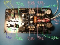
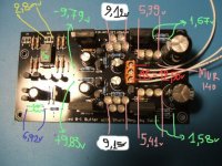
I've measured voltages on AC rails (ca 14,3 V, OK), on led VRef (ca -10,32V, +9,73V) on regulator output (-10,96V, +10,36V).
All relais seems to work as expected, as the input switching.
I suspect that the 2SK170s are broken...
I need help...
Thanks in advance
Hi,
I've just reconnected my DCB1 - Mezmerize and it doesn't work anymore as expected.
If power ground is connected to safety ground it's quite silent with slight hum but music appear a lot attenuated, say 1/50 of the original volume.
If power ground is disconnected a full volume hum with hiss is present (obviously I must shut off the amp suddenly...)
I've measured voltages on AC rails (ca 14,3 V, OK), on led VRef (ca -10,32V, +9,73V) on regulator output (-10,96V, +10,36V).
All relais seems to work as expected, as the input switching.
I suspect that the 2SK170s are broken...
I need help...
Thanks in advance
Measure all four 2sk's on outer pins (drain to source) should be ~10v there.
Measure DC and AC @ output's.
Sounds like a broken ground connection to me...
Measure DC and AC @ output's.
Sounds like a broken ground connection to me...
Hi Tea-Bag
first of all thanks, I've made the suggested measures and all seems fine.
I've measured ground continuity with the DMM in several point (all inputs and output ground vs power ground and all jumpers) and it seems OK.
Broken ground...mmh...Ouch!
I've inverted signal and ground on output cables! 😱
Now it works!
Thanks again you drove me to the solution. 🙂
Indirectly it was a ground issue since you used it for signal by accident. Tea had a good hunch. We haven't had a broken DCB1 since the old first run till now reported by the way. Now I jinxed it, keep em coming!😀


I opalogize if this has been asked before but has any work been added to lower the output impedance so that these could drive headphones .
And with jfet devices of around 10ma idss could be quite difficult to drive an speaker coil, you need CURRENT.I opalogize if this has been asked before but has any work been added to lower the output impedance so that these could drive headphones .
A few days ago, i replaced the CCS resistors with Mills MRA-12 resistors.
2.09v/3.9ohm= 535ma
1.73v/3.5ohm= 494ma
I was previously running at about 350ma....
Well as expected once again i get an improvement in SQ 🙂
The soundstage seems huge on certain recordings, each musician is more easily decernable and can be followed with ease(good seperation) yet they gel and sound very musical. The bass also has gained weight and control and as a result also sounds musical...but the real supprise for me is the treble...Just easier to hear, and REAL sounding!! Adds alot to the experience.
I checked the heat of the mosfets after an hour of listening...fan running at 5v...the mosfets are now hot, but not burning...im easily able to hold my finger on them without having to move away.
HIGHLY RECOMMENDED...especially for those with the Blue Boards.
Alon
Today i changed the 4700uf caps to 10,000uf mundorf caps i also changed the mur120 diodes in the dcb1 and the optivol to fairchild stealth diodes and also added the cl60 thermistor.
An externally hosted image should be here but it was not working when we last tested it.
An externally hosted image should be here but it was not working when we last tested it.
I measured up voltages again and found that the voltage drop accross the ccs resistors was different to what i previously thought i had.
When i first set up my dcb1 with 60ma ccs i measured the voltage drop accross the resistors which were at the time 2.09v and 1.73v, i just assumed that these voltage drops would stay the same when changing resistors.
However today i actually measured the voltage drop accross the resistors. on the -10.10v side i got 1.76v and on the +10.24v side i got 1.39v.
I also measured the resistors values i bought them as 3.9ohm and 3.5ohm what i actually measured was 4.1ohm and 3.7ohm.
So it seems im not actually running at 500ma but instead...
1.76/4.1=429ma
1.39/3.7=375ma
But it still sounds damn good 🙂
And after listening for 2 hours...mosfets are just slightly more then warm...
so how how do i calculate resistor values for running at 600ma, keeping in mind that the voltage accross resistors may again drop???
Thanks Alon.
Last edited:
The Vgs changes incrementally with running current through the Mosfets. There are curves. You either use lower resistors or stronger group 3 Leds to restore target.
Thanks Salas, I will try lower value resistors.
Keith, i got the Salas Shunt reg boards from a member here called Oliver(Dvb-Project)
Here is a link to the details.
http://www.diyaudio.com/forums/group-buys/167414-reference-tda1541a-dac-i2s-bus-architecture.html
Alon
Keith, i got the Salas Shunt reg boards from a member here called Oliver(Dvb-Project)
Here is a link to the details.
http://www.diyaudio.com/forums/group-buys/167414-reference-tda1541a-dac-i2s-bus-architecture.html
Alon
Last edited:
I promised pictures, here they are:
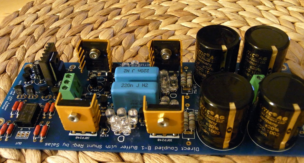
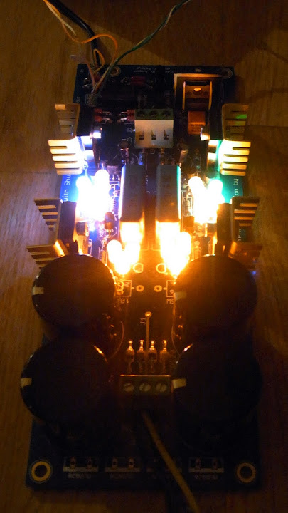
I finally have it boxed, tested, and properly grounded (with a ground loop disconnect - bridge rectifier, power resistor and cap, the works.) Those aren't on the photos, since I closed it up and got tired of unscrewing it 🙂.
I also drilled a few holes in the case, for ventilation, since it could get up to 60 degrees in there. Now it's a fair bit lower, so everything should be at a comfortable temperature.
All photos are In this album.
Again, thanks Nelson, Salas, Tea-Bag and everyone else that worked on this build and helped in the forums.
- Home
- Amplifiers
- Pass Labs
- Building a symmetrical PSU B1 buffer