I think what teabag means is that this thread is about to turn contentious over whether burn in exists or not. Lets avoid that scenario.....
Fran
Fran
and reform electrolytic capacitors that have been stored/transported since manufacture, to bring them back to specification before fitting them to a circuit.Lets avoid that scenario.....
Post a simple rig and instructions or a link here if you may Andrew, its possible some may very well attempt it.
the rig you request consists of a DC power supply with a voltage ~=capacitor voltage rating.
A 100k resistor and three croc ended test leads.
A 63V capacitor will charge initially @ ~0.6mA falling to 0.2mA when the capacitor is ~2/3rds charged.
Leakage will extend the reforming time from <24hrs to infinity, unless you arrange for the charging voltage is exceed the cap rating by a significant margin.
This higher voltage will require much reforming experience with each type and brand of capacitor before you could safely leave them overnight.
Member
Joined 2006
Do I need to adjust anything if I use matched pairs of 2SK79 VFETs? And any benefit to increase the supply voltage? Thx! 😀
Do I need to adjust anything if I use matched pairs of 2SK79 VFETs? And any benefit to increase the supply voltage? Thx! 😀
Very nice and rare semis! You can even build an interesting SRPP line preamp with those VFet as published on MJ several years ago.
The leds that I got from farnell (per the BOM) al measure around 1.72V using a 9V battery and 1K2 resistor. Making matched strings will be easy but they will be a bit lower than advised.
What is the margin for the string values?
Thanks,
Jeroen
What is the margin for the string values?
Thanks,
Jeroen
The 3 led strings are upping the current as much as they widen from CCS Mosfet Vgs and vice versa. In your case you just may get a little less current running in the regs, which is a multiple of what is needed anyway by enough times.
The Vout gave me enough contention around the 10V mark +/- 0.5V-1V. That is not about working, it could work in a wide range.
The Vout gave me enough contention around the 10V mark +/- 0.5V-1V. That is not about working, it could work in a wide range.
Wow, that is quick. Thanks!!
I must say, support here is brilliant. 😀
(Few more hours of work and than back to heating the iron...)
I must say, support here is brilliant. 😀
(Few more hours of work and than back to heating the iron...)
Member
Joined 2006
Very nice and rare semis! You can even build an interesting SRPP line preamp with those VFet as published on MJ several years ago.
Thanks massimo, will put this together first once Tea-Bag's board is in. Yeah, could try out the SRPP or the CCS version later, should be easy to swap around 😀 BTW, could you point out the link to that MJ article if available on line? 😛
I don't think you can find MJ's articles on line, but it was published on MJ 2002/6. If you can read Japanese, I could scan the whole article and send you by email.
3 years ago I briefly described the schematics here: http://www.diyaudio.com/forums/pass-labs/75326-j-fet-zen-srpp.html see post #14
3 years ago I briefly described the schematics here: http://www.diyaudio.com/forums/pass-labs/75326-j-fet-zen-srpp.html see post #14
Another one is alive. 😎
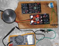
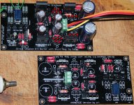
I used the parts from the BOM and matched 170's from Spencer and all worked the first time. The output shows 0 to 1 mV.
The unit tested ok on my 6v6SET. I listened just for a few minutes as it a test setup so I have no listening impression yet.
And now for the casing...
Thanks for this project!!
Jeroen
Attachments
You are welcome. We will be glad to learn about your impressions and also about any ''run in'' differences as those experienced by Fran and Udaily. So to know if its a systematic thing or not.

Member
Joined 2002
case, from here 🙂
Chassis case item
Im going to be buying 1 of these for my B1,
Chassis case item
Im going to be buying 1 of these for my B1,
An externally hosted image should be here but it was not working when we last tested it.
An externally hosted image should be here but it was not working when we last tested it.
Last edited:
case, from here 🙂
Chassis case item
Im going to be buying 1 of these for my B1,
An externally hosted image should be here but it was not working when we last tested it.
An externally hosted image should be here but it was not working when we last tested it.
Very nice case/chassis. I'd be interested in a few...
How about a group buy on these cases? I'm sure we can set that up.
Member
Joined 2002
Very nice case/chassis. I'd be interested in a few...
How about a group buy on these cases? I'm sure we can set that up.
I tried that no one was interested.
see,
http://www.diyaudio.com/forums/group-buys/154291-pre-poweramp-case-group-buy.html#post1993005
- Home
- Amplifiers
- Pass Labs
- Building a symmetrical PSU B1 buffer