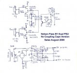
Although I did mail the mods to separate the info on a symmetrical B1 from the standard B1 thread this wasn't done. Info on the symmetrical B1 confused some people so I opened a new thread. Making the B1 with symmetrical ( +/-) supplies makes it possible to go capless or DC-coupled with the B1. Since 99% of standard equipment has out- or input caps this will be beneficial as long as you know what you are doing. So it is not exactly without risks. You've been warned. These are some points as quoted by Salas:
1. By trimming the supplies a bit non symmetric, the output offset falls to either zero or under half mV, steady. It counteracts naturally non perfectly alike JFET pairs.
2. If the applications situation can be non safe (general tests use with possibility of unknown non DC offset checked sources?), an input capacitor only can be used. It will be small value and can be even Teflon and rather affordable. That will obviously guard against most of the danger scenarios and will still be cheaper and more transparent than having an additional big output quality cap. The DC coupled output will not deviate to non safe, unless one psu ceases when in service, or the input resistor to ground is not used and a pot becomes dodgy. Always use that resistor, does good to the pot's transparency too. Hence, a non issue.
3. Each one to his own risks. Situation is well reviewed.
4. Benefits are: Much cheaper, audibly more neutral, more compact.
5. Risks are: If you are not careful and there is no input capacitor in your power amplifier, or DC output sensor and relay, you can burn woofers, if you connect a source device with much DC offset, or one symmetric B1 supply fails during service. Be warned.
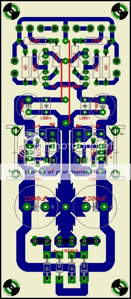
I hope something nice will be created with the schematic Salas designed. Crt ( La Ode ) did a design on the PCB which is not 100 % finished but it is useable.
1. By trimming the supplies a bit non symmetric, the output offset falls to either zero or under half mV, steady. It counteracts naturally non perfectly alike JFET pairs.
2. If the applications situation can be non safe (general tests use with possibility of unknown non DC offset checked sources?), an input capacitor only can be used. It will be small value and can be even Teflon and rather affordable. That will obviously guard against most of the danger scenarios and will still be cheaper and more transparent than having an additional big output quality cap. The DC coupled output will not deviate to non safe, unless one psu ceases when in service, or the input resistor to ground is not used and a pot becomes dodgy. Always use that resistor, does good to the pot's transparency too. Hence, a non issue.
3. Each one to his own risks. Situation is well reviewed.
4. Benefits are: Much cheaper, audibly more neutral, more compact.
5. Risks are: If you are not careful and there is no input capacitor in your power amplifier, or DC output sensor and relay, you can burn woofers, if you connect a source device with much DC offset, or one symmetric B1 supply fails during service. Be warned.
I hope something nice will be created with the schematic Salas designed. Crt ( La Ode ) did a design on the PCB which is not 100 % finished but it is useable.
Attachments
I was to split it, but I was waiting for the full works from La Ode. He sent me the last stuff just today evening.
The idea started very early in the B1 thread by a ZenMod suggestion. Link.
Then I took it a bit further.
Link.
And I actually made it in P2P.
Link.
This year, interest came back and La Ode made it on a nice PCB.
He is planning a full monoblock version with delay relays and four supplies.
*Actually because the symmetric stuff is scattered in a very long thread in a year long span, maybe the initiative of a new thread is better since a late split would make the original thread incoherent around those posts.
The first he has made was without delay relays, its the simplest to make. Has common supplies between channels. Actually 220R gate stoppers and output resistive buffers worked just fine.
There are Eagle files too, but I would ask LaOde to give us the dimensions in mm so for those who will use print and transfer to know the scale. I prefer not to post the Eagle files so not to give ready made food to commercial rippers, since this is good work for DIY use ONLY.
forgot:
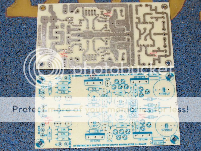
the dimension of PCB is 122,0 mm x 53,5 mm
i still working with new layout of symetric b-1 buffer with shunt. reg (by salas too).
@salas
Check your e-mail.
regards
La Ode
the dimension of PCB is 122,0 mm x 53,5 mm
i still working with new layout of symetric b-1 buffer with shunt. reg (by salas too).
@salas
Check your e-mail.
regards
La Ode
wohooooo
the new symetric B-1 Buffer with Shunt Regulator PCB is done
maybe tomorrow i can finished the job
Thank's Salas
the new symetric B-1 Buffer with Shunt Regulator PCB is done
maybe tomorrow i can finished the job
Thank's Salas
Hi Salas,
Great project but
..............think shunt! I built this with a small shunt regulators with great results all it took was a small current source and a zener.
Jam
Great project but
..............think shunt! I built this with a small shunt regulators with great results all it took was a small current source and a zener.
Jam
Crt says he could hear the difference in moving up from series regs to shunt regs right away.
He wrote enthusiastically about the subjective performance in an email to me, but I will let him listen more and tell it by himself.
Here is the design in detail.
He wrote enthusiastically about the subjective performance in an email to me, but I will let him listen more and tell it by himself.
Here is the design in detail.
Attachments
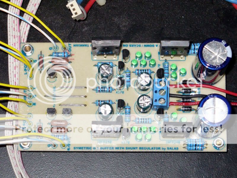
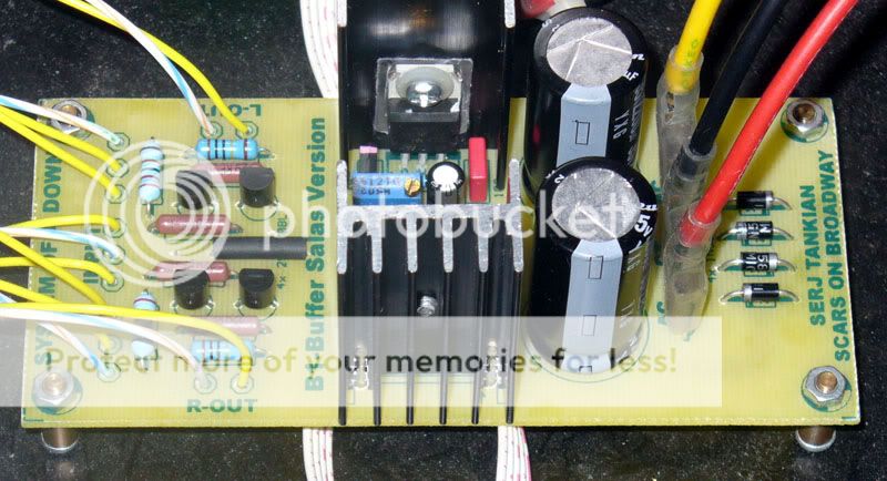
Hi Salas and Crt. The symmetrical B1 becomes mature. How about the need for heatsinks on the transistors ?
I have calculated that with 60mA CCS per rail (68R//68R=R1) there is no danger at 10V. 60-17mA per rail times 10V for each shunt element = 430mW each. +/- 17mA runs in the audio circuits. No problem for T0-240 devices like those used.
Crt uses 3X68R in parallel, so about 100mA CCS with his 1.87V Leds, at about 11V (1.87Vf gets him a bit high here too). About 1W then.
Nothing burned (50C), but being cautious, he added those:
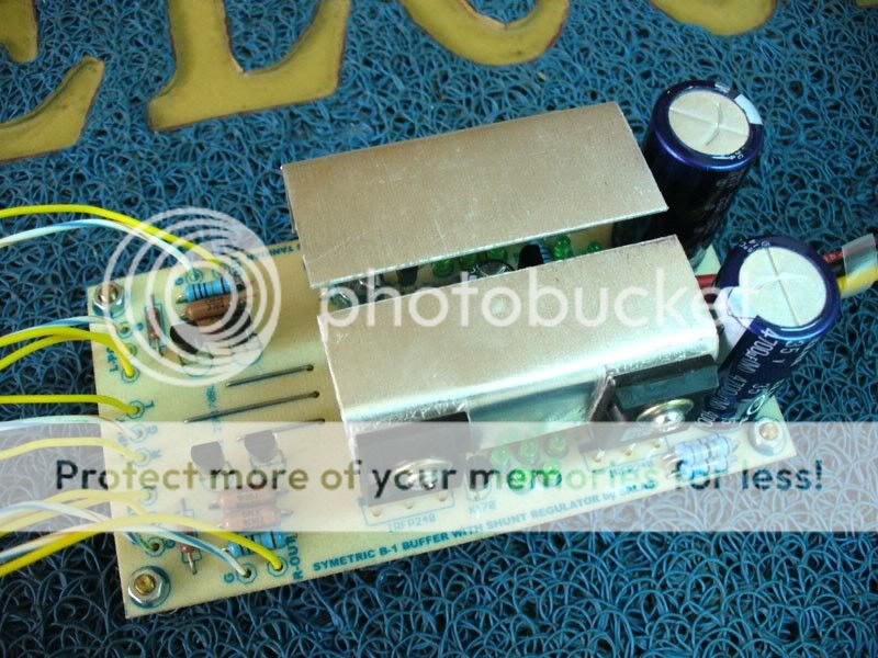
Just use R1=34R, and no worries.
Crt uses 3X68R in parallel, so about 100mA CCS with his 1.87V Leds, at about 11V (1.87Vf gets him a bit high here too). About 1W then.
Nothing burned (50C), but being cautious, he added those:
Just use R1=34R, and no worries.

slightly oftopic
Is it possible to use just pos shunt reg with original "singleend" B1
ehhh, probably not
🙄
Is it possible to use just pos shunt reg with original "singleend" B1
ehhh, probably not
🙄
It is quite comical to see that ( after separating the"symmetrical" thread from the normal B1 thread ) questions about the normal version arise in this thread 😉
It should work but it should be made for the right voltage of standard B1. AFAIK this was discussed in another thread:
http://www.diyaudio.com/forums/showthread.php?s=&threadid=143693
I just found out that the Search function really works effectively nowadays ! A change for the better.
It should work but it should be made for the right voltage of standard B1. AFAIK this was discussed in another thread:
http://www.diyaudio.com/forums/showthread.php?s=&threadid=143693
I just found out that the Search function really works effectively nowadays ! A change for the better.
- Home
- Amplifiers
- Pass Labs
- Building a symmetrical PSU B1 buffer