Hello diyers,
I would like to build a DAC based on 4x TDA1387 but I don't know which parts and sections I'll need, since I'm starting to understand how a NOS DAC actually works. There are some good quality ready-made boards available online, but I need to build it very small, minimalist style for a portable application, so I must build it from scratch.
Digital data and MCLK would come via I2S from an ARM MC (Teensy4).
My initial question is which sections this DAC should include. To my understanding an LPF and a voltage to current (VI) converter are needed at the output of the DAC paralleled ICs, the latter can be an opamp or inductor network. Which other sections would I minimally need, provided PSU and MCKL are already there? I think a TTL IC might still be necessary for it work in slave mode, but still don't understand it's function so I'm not sure about it.
I'm trying to get a broad view on what does it mean to embark in this project. I don't need the best quality ever, but that it works decently for monitoring audio to be recorded. If anybody has seen a circuit diagram for this DAC with components, that would be very helpful. There is a 4x board around but it's USB and undocumented. I haven't found any diagram on the 8x chip I2S board neither. Any contribution will be highly appreciated.
Regards and cheerful Christmas (specially for those who celebrate),
Domingo
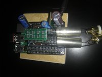
I think it's a great DAC for a first time DAC build project. I went with the TDA1387 8x TDA1541 replacement boards sold on eBay. The design can be as simple as passive IV, depending on what it is driving. I started with a minimalist build. Using an RPi Proto HAT board, two IV resistors 470R-500R, output coupling caps 10uF film, and 470R series resistors for I2S. I2S straight from the RPi GPIO. Powered using an LT1963 (7805) converter module with additional caps. The Vdd cap value effects the sound quality, so get a good audio grade electrolytic here. With the 8x module, C3 and C4 are the datasheet values and SMD ceramic. But, that's it. Try that to start, and add sophistication as needed. Great sounding DAC in my system.
Attachments
Last edited:
You don't say what kind of output you need from your DAC. For example, headphone drive? Or just feeding into an external amp?
You don't need MCLK for driving TDA1387. Seeing as you're using a very powerful 600MHz ARM Cortex M7 you could run oversampled (2X or 4X wouldn't eat into your CPU horsepower very much).
You don't need MCLK for driving TDA1387. Seeing as you're using a very powerful 600MHz ARM Cortex M7 you could run oversampled (2X or 4X wouldn't eat into your CPU horsepower very much).
1541A board only uses the following pins:
Pins 1, 2, 3 I2S
Pin 28 Vdd
Pin 5 GND
Pin 6 Right output
Pin 25 Left output
Pins 1, 2, 3 I2S
Pin 28 Vdd
Pin 5 GND
Pin 6 Right output
Pin 25 Left output
1541A board only uses the following pins:
Pins 1, 2, 3 I2S
Pin 28 Vdd
Pin 5 GND
Pin 6 Right output
Pin 25 Left output
Thank you for your answers!
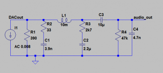
What kind of passive IV circuit did you use @hifiamps? Same topology as in the attachment (taken from @abraxalito himself in another thread)?
This is to drive a cmoy headphone amp @abraxalito (on AD8620). Oversampling is a good idea to consider in the future, but I need to keep this as simple and transparent as possible, since it is for audio recording monitoring. So hopefully minimum LF/HF rolloff or boost.
Can I stack the chip together up (ie. x4) and share only one Vf cap for all of them? The data sheet recommends 1uf, but I suppose using a common one should increase the value. Most builds are going for 1000uf for each chip.
And how is the MCLK not necessary, if the x8 board comes with its own crystal clock? If I feed a TDA1387 stack directly from the ARM's generated LRCLK (44.1KHz) and BCLK (1.41MHz) to corresponding TDA's BCK and WS pins it will work out of the box? 🙂
Anyways after your answers I feel very optimistic about it.
Wishing you a nice coming week,
Domingo
Attachments
This is to drive a cmoy headphone amp @abraxalito (on AD8620). Oversampling is a good idea to consider in the future, but I need to keep this as simple and transparent as possible, since it is for audio recording monitoring. So hopefully minimum LF/HF rolloff or boost.
The reason behind suggesting OS was to minimize the 'droop', if you run NOS you'll lose ~3dB at 20kHz. Either live with that or build another stage to boost the HF back to flatness again. That extra stage stands a good chance of losing you some transparency. Of course with your M7 you could implement digital EQ to give you the necessary boost, it will be less complex to implement than OS. I once made a 'droop corrector' with a 3-tap FIR filter.
I think that's OK yes. 1000uF for each chip might prove a bit bulky in a portable application.Can I stack the chip together up (ie. x4) and share only one Vf cap for all of them? The data sheet recommends 1uf, but I suppose using a common one should increase the value. Most builds are going for 1000uf for each chip.
And how is the MCLK not necessary, if the x8 board comes with its own crystal clock? If I feed a TDA1387 stack directly from the ARM's generated LRCLK (44.1KHz) and BCLK (1.41MHz) to corresponding TDA's BCK and WS pins it will work out of the box? 🙂
I dunno what the full schematic of the x8 board is but I did have one on my desk for a while, sent to me by another DIYer. The crystal osc there is being used for 'asynchronous reclocking', something I don't recommend. I bypassed it before returning the board to its owner, its unnecessary to the operation of the module.
Yes if you send BCK @ 1.4MHz and LRCK/WS at 44k1 then you'll have the right ingredients to get sound out of your TDA1387.
The passive IV circuit is as simple as it gets. IV resistors to ground. I don't have any post-DAC filtering. But since you are using it for a critical application, you will probably want to achieve a flat response in the final circuit. @abraxalito is the expert here. I'm suggesting to begin with the simplest prototype, and have a listen.What kind of passive IV circuit did you use @hifiamps?
I think the best SQ at pin 7 is with a high quality 1 uF film cap (with the active IV Garman DAC). I do have experience with the TeraDak. I think 1000 uF on pin 7 reduces accuracy and 3D. It is very detailed, but the orchestra/ensemble sounds stacked at the front of the stage.Can I stack the chip together up (ie. x4) and share only one Vf cap for all of them? The data sheet recommends 1uf, but I suppose using a common one should increase the value. Most builds are going for 1000uf for each chip.
Without a Vdd cap (just the voltage regulator), the sound is extremely three dimensional, but very anemic, lacking bass and dynamics. I am currently using a 1000 uF, which seems to be a good compromise. You should experiment with the Vdd and pin 7 caps.
Last edited:
Do you mean @hifiamps that the IV filter you use is the same I posted in attachment before? Or something even simpler than that? :s
For simplicity (space) I’m prone to use an opamp as IV (AD712 is what I have), but I don’t know how it will affect transparency compared to a passive inductor based IV. I think I read opamp IV tends to compromise LF (bass), but I would appreciate some confirmation because my board space is very limited and this would be a convenient solution for me. Also, the datasheet recommend values of 1.5n cap and 2.7k for the opamp, but that’s probably counting on a single TDA1387’s output current. In what way should I modify those values when using 4 paralleled chips? I guess resistor should be 4 times smaller and cap adapted to play as LP filter at around 44.1Khz, but I’m guessing there.
Thanks for the clarification on the oversampling @abraxalito. I like the idea of a FIR filter to compensate the droop effect. Using an IC with incorporated EQ filters like the SGTL5000 for Teensy is trivial, but I’m not using that chip precisely because I’m looking for a better quality ADC/DAC solution and I don’t know if implementing the filter directly on the M7 is at my hand. Besides my basic knowledge programming in C, I would need audio to be simultaneously recorded without the FIR written on it. But I keep it mind as the cherry on the cake and will watch over the droop effect I’ll get. I appreciate the warning.
Already looking forward to receive the chips and experiment all I can 🙂 I thank you both for sharing your precious knowledge, for me and the sake of good sound.
I am not using an IV filter. I go straight from the IV resistor to the output cap. No filter. So it does not have a low pass filter at all. I think you should try it that way first. I suppose it has the sinc droop -3dB at 20kHz, but it sounds excellent to me. You could upsample 44.1 to 88.2 to make the response flat, but 16/44.1 sounds best to me as is, without upsampling. I'm not sure why that is the case. BTW: 24/96k and 24/192k sound excellent with this DAC, even though the lowest 8 bits are truncated.Do you mean @hifiamps that the IV filter you use is the same I posted in attachment before? Or something even simpler than that? :s
I generally try to avoid filters if they are not needed, and if they are needed, keep the fc well out of the audio range if possible.
For simplicity (space) I’m prone to use an opamp as IV (AD712 is what I have), but I don’t know how it will affect transparency compared to a passive inductor based IV. I think I read opamp IV tends to compromise LF (bass), but I would appreciate some confirmation because my board space is very limited and this would be a convenient solution for me. Also, the datasheet recommend values of 1.5n cap and 2.7k for the opamp, but that’s probably counting on a single TDA1387’s output current. In what way should I modify those values when using 4 paralleled chips? I guess resistor should be 4 times smaller and cap adapted to play as LP filter at around 44.1Khz, but I’m guessing there.
The TDA1387 puts out 1mA peak-to-peak current, a 2k7 feedback resistor is fine if you want 1VRMS output from a single DAC chip. For 4 chips, divide the value by 4 as you've guessed. Based on my experience I'd make the cap across that feedback resistor just large enough to prevent the opamp going into slew-rate limiting, but no larger. So its value will depend on the slew-rate of the opamp you're using.
I generally try to avoid filters if they are not needed, and if they are needed, keep the fc well out of the audio range if possible.
Is the following diagram interpreting correctly the minimal setup that you have @hifiamps?
Any mistakes or corrections to do? I'm not sure about the VDD cap, should it be an audio grade high value electrolytic or 100n film cap. Also, what kind of IV resistors are you using? Film? Your output caps seem very extraordinary too. What I have available here is mostly Nichicon electros and Wima MKS of all values up to 4,7U. Also some 1UF MKP are laying around 🙂 My resistors are all metal 1% tolerance. Anyways, I can always get additional parts may they make an importance difference.
PD: Please notice that I'm paralleling 4 chips.
Attachments
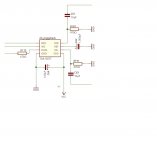
The circuit diagram looks correct except for 4x TDA1387 you need ~1k ohm IV resistor (R181, R191). The 470R is appropriate for 8x, as abraxalito stated above. Traditionally, MLCC are used for C64 and mounted as close as possible to the chip. I think you would need only one for your stack of four TDA1387. An acrylic film SMD may be better. Adding a 1uF acrylic film SMD cap in parallel to C64 is beneficial. Can the stack of four TDA1387 share C62? I'm not sure. The 8x module has individual C64 and C62 for each TDA1387. The 4x module also uses individual caps. I use a 1000 uF audio quality electrolytic for Vcc mounted close to the 8X module. The output caps are very important for sound quality. The WIMA MKS 4.7 uF looks like your best bet. But since you are looking for the most compact package, a Silmic II electrolytic would be much smaller. Another possibility might be to somehow remove DC offset to enable direct coupling, and completely eliminate the output coupling caps. I'm not sure if this can be done in passive IV, but it can be done with active IV. Abraxalito probably knows the answer.
Forgot to mention. I use a 470R mounted close to each of the I2S pins (BCK, WS and DATA) to reduce noise. It worked even with 8 inch jumper leads on a proto board.
Regarding the WIMA MKS, I think it is a polyester cap, and not good for sound quality as a coupling cap. It will sound harsh, but you can use it in a pinch for a proto build. WIMA MKP is polypropylene and much better, but larger for value and more expensive. The Silmic II are very small, being electrolytic, reasonably priced and sound very nice. Polypropylene film cap is the best for SQ at a reasonable price, but large physical size could be a deal breaker in your application. 10 uF with a typical 10K load creates a high pass fc of 1.59 Hz and 4.7 uF is 3.4 Hz, which is fine.
Regarding the WIMA MKS, I think it is a polyester cap, and not good for sound quality as a coupling cap. It will sound harsh, but you can use it in a pinch for a proto build. WIMA MKP is polypropylene and much better, but larger for value and more expensive. The Silmic II are very small, being electrolytic, reasonably priced and sound very nice. Polypropylene film cap is the best for SQ at a reasonable price, but large physical size could be a deal breaker in your application. 10 uF with a typical 10K load creates a high pass fc of 1.59 Hz and 4.7 uF is 3.4 Hz, which is fine.
Last edited:
For the 1000 uF Vcc cap (you need to experiment with the value to get the sound to your liking), try the Nichicon KA, which are reasonably priced and sound very nice in that position. You always need to use a 100 nF MLCC (multilayer ceramic capacitor) mounted as close as physically possible to the leads to eliminate ringing. Film caps could be used here instead of the MLCC, but at much larger size and greater cost. Notice that the 4x module above uses a polyester film cap (blue box). Consideration for a down-the-road refinement. The acrylics and PPS are surface mount and very small.
Last edited:
Thank you @hifiamps, I attach diagram with resistors corrected for the record. I'll try first with a 100u VDD cap, then move to 1000u if necessary. Plenty of information to experiment 🙂
It came to me the idea of combining (for size reasons) an active IV with the headphone amp I was planning to use anyways after, which is no more than an inverting opamp. The idea is in picture "version 2". I don't know if this would work. What do you think @abraxalito ? Feedback resistor (R210 & 225R) is 660ohm (2.7k / 4). The 66ohm to ground should provide a gain of 11. Feedback cap (C66 & C67) follow the datasheet value of 1.5n as per datasheet, as I don't know how to calculate the maximum size before going into slew-rate limiting (50 V/μs @ AD8620).
It came to me the idea of combining (for size reasons) an active IV with the headphone amp I was planning to use anyways after, which is no more than an inverting opamp. The idea is in picture "version 2". I don't know if this would work. What do you think @abraxalito ? Feedback resistor (R210 & 225R) is 660ohm (2.7k / 4). The 66ohm to ground should provide a gain of 11. Feedback cap (C66 & C67) follow the datasheet value of 1.5n as per datasheet, as I don't know how to calculate the maximum size before going into slew-rate limiting (50 V/μs @ AD8620).
Attachments

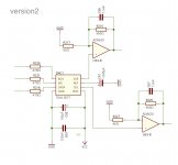
Your version 2 schematic has the current outputs of the DACs going to the +ve input of the opamps as if the DAC's outputting a voltage. The DAC current outputs need to see a low impedance hence they go to the opamp -ve inputs. The gain at the output is set by the feedback resistor, no need for the 66Rs.
Are you running only a single 5V supply for the AD8620s? If so then the opamp's +ve inputs need biassing at some positive voltage to be calculated. [later] After looking at the DS for AD8620 I see its not a single rail design, its lowest operating voltage is +/-5V. So you'll need a -5V supply.
Are you running only a single 5V supply for the AD8620s? If so then the opamp's +ve inputs need biassing at some positive voltage to be calculated. [later] After looking at the DS for AD8620 I see its not a single rail design, its lowest operating voltage is +/-5V. So you'll need a -5V supply.
I see now that I need an inverting amplifier for IV. Thanks for the observation. The AD8620 is indeed dual rail and I'm planing to feed it with a rail split opamp configuration, which I use in other parts of the circuit to feed other dual rail mixers. The split however provides +/-6v max. and +/-4.5v min. depending on battery state (3 lithium batteries in series). Quite on the edge. Could you suggest me any lower voltage dual rail opamp to play the role of IV and headphone amp simultaneously (up to 100ohm impedance cans)? Or would it be better a single rail within the range +12v max. +9v min.? And since the cmoy wouldn´t work here, would a simple opamp in inverting configuration suffice to drive the headphones?
- Home
- Source & Line
- Digital Line Level
- Building a portable I2S 4x TDA1387 DAC