
@Dneu2011 is 100% correct… @rhthatcher has a board that’s absolutely perfect for Pearl 2. Shoot him a PM
I had provided @rhthatcher the gerber files for my PCB so Im curious if we’re referring to the same one or something else that he had made
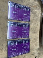
I found two of these in the “hoarding drawer”. Who did I get these from? I’m happy to let one go if there’s a need.
Edit:
Looks like I purchased them from @itsikhefez. I found the order from 3 years ago.

Original thread:
https://www.diyaudio.com/community/...aps-bridge-rectifier-for-pass-pearl-2.370142/
Edit:
Looks like I purchased them from @itsikhefez. I found the order from 3 years ago.
Original thread:
https://www.diyaudio.com/community/...aps-bridge-rectifier-for-pass-pearl-2.370142/
Last edited:
I’m out of my Pearl 3 style boards. But I found these in my stash.
Free + shipping.
These are @itsikhefez design and work very well.
@sacakl - I sent you a PM
Free + shipping.
These are @itsikhefez design and work very well.
@sacakl - I sent you a PM
Attachments
Hey guys -- Looks like I'm covered on the board. Thanks so much, and thanks @rhthatcher and @itsikhefez ! I'll post here if I have any questions about the build. Much appreciated!
I have a Pearl 2 that is connected to an ACP+ being used as headphone amp. When I connect a turntable with a Denon DL103 through a Step Up transformer to the Pearl 2/ACP+ combination I seem to be getting overload. The SUT is 1:10 and the DL103 has .3mV output, so about 3mV going into the Pearl 2. I'm using the standard configuration for the Pearl 2 so I believe it has 55dB gain. If my calculations are correct, the output of the Pearl 2 will be about 170mV. My question is: am I overloading the Pearl or the ACP+?
BTW, if I use an SUT with 1:7.5 ratio I don't seem to be getting overload. The problem with this is the cart sees about 850 ohm load which is a bit to much (target for that cart is 400 ohm in my experience). I know that I can add a resistor to the Pearl 2 to drop input impedance and will do so if the 1:10 SUT is too much.
Thanks for your thoughts.
Yes, I wondered about that. Just use a loading resistor directly in the Pearl.You don't need a step-up transformer with the Pearl 2.
That spot (R20) on the PCB is open - so just the base 47k input impedance (which of course is too high for the DL103 or any MC cart. It sounds like the solution is just to add sockets for R20 (optional loading resistor) so I can refine the cart loading.What loading resistor are you using with the 1:10?
So it sounds like the solution is to omit the SUT and just add loading resistor. It's interesting that I've had this Pearl for at least 7 years and used it with other MC carts, sometimes with an SUT, albeit low ratio and often much lower cart output. It's a great sounding phono section I've recently finished the Pearl 3 but haven't cased it yet, so it's not in a system
Thanks to all for the assistance.
Thanks to all for the assistance.
Hello everyone, I understand that our community is busy with Pearl3 now, but I would like to simplify the DIY activities of those like me who admire Pearl2 a bit:
1. Setting the voltage drop/current on R6 to around 1.65V helped to select U1 and U2 (Vu1=IVu2I+-0.1V).
2. To reduce the voltage on collector Q3 to 400-350 ohms, slightly more than on the base of the sluggish R9. Left channel 400, right channel 350.
3. Optionally, as already described here - sorry, I had to look for someone for a long time - reduce R10 to 6K8.
I hope that this saves someone a couple of hours.
I will post the photos in a separate report.
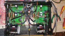
The motto when building the Pearl was: "It doesn't have to be pretty, but it doesn't have to be a compromise in terms of sound", at least that's what I can imagine.
And that's what it sounds like!
Thanks and greetings to everyone.
1. Setting the voltage drop/current on R6 to around 1.65V helped to select U1 and U2 (Vu1=IVu2I+-0.1V).
2. To reduce the voltage on collector Q3 to 400-350 ohms, slightly more than on the base of the sluggish R9. Left channel 400, right channel 350.
3. Optionally, as already described here - sorry, I had to look for someone for a long time - reduce R10 to 6K8.
I hope that this saves someone a couple of hours.
I will post the photos in a separate report.
The motto when building the Pearl was: "It doesn't have to be pretty, but it doesn't have to be a compromise in terms of sound", at least that's what I can imagine.
And that's what it sounds like!
Thanks and greetings to everyone.
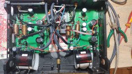
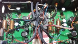

So, with this rotary switch in the middle I combined MM/MC regime.
The resistors for MC are 30-100-200-500-1000.
thanks
The resistors for MC are 30-100-200-500-1000.
thanks
Hello dezibaby,
the PEARL 2 is still a fantastic phonostage. I also still have mine and listen to it. And there is also still a PEARL 1 and an Aleph XONO.
But My focus was on the PEARL 3 for the last few weeks.
Cheers
Dirk
p.s.: don't forget to rotate the phase with the PEARL 2 - but you will know that. Outputphase is inverted.
Hello cubicincher,
yes I know about phase shifting, but maybe I don't fully understand:
I thought that if both channels are connected the same way, it loses its meaning, because they are ultimately transformers and they are non-polar.
Thanks
yes I know about phase shifting, but maybe I don't fully understand:
I thought that if both channels are connected the same way, it loses its meaning, because they are ultimately transformers and they are non-polar.
Thanks
Just finished boards and PSU and was trying to connect it to the stereo.
One channel played - the other did not.
I would start to suspect the ZVP3310 as I have read it is causing problems for many.
How Can I know that Q2 (ZVP3310) is working?
Will a Voltage drop across R29 (100 ohm) at 1.14V indicate that when about 11 mA flows through this resistor - then Q2 is working?
Sorry for my last post.
The problem was the wiring 🤯
I had switched ground and signal for one channel.
In Denmark we have a saying that translates to something like” the eyes are where you first get blind” - and right now I feel rather blind that I didn’t see that before starting all the voltage measuring.
The problem was the wiring 🤯
I had switched ground and signal for one channel.
In Denmark we have a saying that translates to something like” the eyes are where you first get blind” - and right now I feel rather blind that I didn’t see that before starting all the voltage measuring.
Attachments
- Home
- Amplifiers
- Pass Labs
- Building a Pearl 2