The power supply generally looks OK.
I would check the polarity of the connectors and conductors of the umbilical to ensure "plus" is still "plus" etc. when you connect to the board. You might want to standardize on referencing voltages to ground (your black wire on the meter)... just a suggestion.
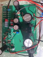
Pics of the Pearl boards at the regulators would help now.
I would check the polarity of the connectors and conductors of the umbilical to ensure "plus" is still "plus" etc. when you connect to the board. You might want to standardize on referencing voltages to ground (your black wire on the meter)... just a suggestion.
Pics of the Pearl boards at the regulators would help now.
Thanks for all the advices. I will move on to the Pearl boards.The power supply generally looks OK.
I would check the polarity of the connectors and conductors of the umbilical to ensure "plus" is still "plus" etc. when you connect to the board. You might want to standardize on referencing voltages to ground (your black wire on the meter)... just a suggestion.
Pics of the Pearl boards at the regulators would help now.
Can you please explain a little more what you meant by this:
"You might want to standardize on referencing voltages to ground (your black wire on the meter)... just a suggestion."
Did you mean the color of the wires?
No, I'm talking about the meter probes (wires). If you consistently use the "COM" (black) probe attached to ground then your meter will not only measure the amount of voltage but the polarity (+/-) too.
Try it on the power supply. One measurement will be positive (32VDC) and one will be negative (-32VDC). This is important info.
Try it on the power supply. One measurement will be positive (32VDC) and one will be negative (-32VDC). This is important info.

Hey shomescu, how's it goin'?
I was wondering if you could help me understand the CRC choices in your power supply.
Could you please measure the voltages on either side to the 10 ohm resistors? And measure the AC voltage across the transformer secondaries?
Your transformer is rated at 2 x 22VAC right?
I'm trying to decide whether I need a new transformer or whether to use what I have (a 2 x 24V) and pad it down.
Thanks!
WIth a bit of delay because I can only work during the weekend I have finished the check for one board, the one with red LED working.No, I'm talking about the meter probes (wires). If you consistently use the "COM" (black) probe attached to ground then your meter will not only measure the amount of voltage but the polarity (+/-) too.
Try it on the power supply. One measurement will be positive (32VDC) and one will be negative (-32VDC). This is important info.
I have attached:
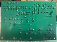
- back of the board pic
- front of the board
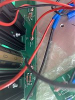
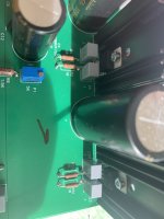
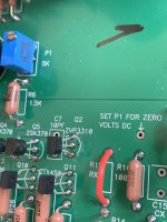
- close up at the regulators - both sides
- close up at Q2
With the meter leads - black in COM and red in V/ohm/mA I am measuring:
- red probe to +DC IN (red wire on the board) and black probe to -DC IN (black wire on the board) : 56.8 V
- red probe to +DC IN (red wire on the board) and black probe to PAD2 GROUND (red wire on the board) : 30.1 V
- black probe to -DC IN (black wire on the board) and red probe to PAD2 GROUND (red wire on the board) : 26.9 V
- red probe to R3/R4 and black probe to PAD2 GROUND (red wire on the board): 23.8 V
- black probe to R31 / R33 and red probe to PAD2 GROUND (red wire on the board): 24.6 V
- I also measured across outside legs of Q2 the current: 12.6 mA
Anything else to check?
Attachments
Hello mhenschel,Hey shomescu, how's it goin'?
I was wondering if you could help me understand the CRC choices in your power supply.
Could you please measure the voltages on either side to the 10 ohm resistors? And measure the AC voltage across the transformer secondaries?
Your transformer is rated at 2 x 22VAC right?
I'm trying to decide whether I need a new transformer or whether to use what I have (a 2 x 24V) and pad it down.
Thanks!
I measured today.
Across the secondaries: 24.8 V
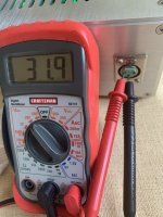
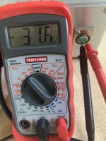
Either side of the 10 ohm resistor I measured 31.8V
Yes, my transformer is rated 2x22V.
Anything else I can help you with?
A couple of things:
You seem to be leaking voltage between the PSU and the preamp boards. I don't believe you should be dropping a volt on the positive side and you really shouldn't be dropping the 3 volts on the negative side.
What is the voltage at the output XLR pins of your supply? Remember -- COM on the meter should be applied to the GROUND (the colour of the wire doesn't matter but black is the convention) and the voltages taken in reference to that common ground basis.
More importantly, I think you probably need to examine your solder joints. A lot of them look "cold" to me. And it's hard to tell, but there might be whiskers of solder between pads. There is certainly flux that ought to be cleaned off. That might be the problem.
Hope this helps.
I have 31.8 V on each side and 63.7V in total with no load on the PSU.A couple of things:
You seem to be leaking voltage between the PSU and the preamp boards. I don't believe you should be dropping a volt on the positive side and you really shouldn't be dropping the 3 volts on the negative side.
What is the voltage at the output XLR pins of your supply? Remember -- COM on the meter should be applied to the GROUND (the colour of the wire doesn't matter but black is the convention) and the voltages taken in reference to that common ground basis.
More importantly, I think you probably need to examine your solder joints. A lot of them look "cold" to me. And it's hard to tell, but there might be whiskers of solder between pads. There is certainly flux that ought to be cleaned off. That might be the problem.
Hope this helps.
I was thinking that 30.1V and 26.9V is because of the PSU being connected to the preamp board?
No specialist in this area...I rely on the help from this forum.
In the weekend will clean and inspect the solder joints again.
Do you have any idea why one regulator becomes hot and one not? Is the hot one normal and you guys have the same in your board?
Since I was able to measure current flowing Q2 is there anything else to be checked to consider this board is functional?
Thanks
As mhenshel mentioned, something seems to be pulling a lot of current on the negative rail which may be why you are only
seeing -26.9V at the pad for V-. Try measuring the voltage across the R30 and R31 resistors. That will give
you an estimate of the current draw on the negative rail.
What DC offset voltage are you seeing, before the C13 output cap? (COM/black probe on GND and red probe
at R17/C13 junction)
Also please check the voltages across R28, R29 and R25 and R6.
I measured the following - with the black probe on GND:As mhenshel mentioned, something seems to be pulling a lot of current on the negative rail which may be why you are only
seeing -26.9V at the pad for V-. Try measuring the voltage across the R30 and R31 resistors. That will give
you an estimate of the current draw on the negative rail.
What DC offset voltage are you seeing, before the C13 output cap? (COM/black probe on GND and red probe
at R17/C13 junction)
Also please check the voltages across R28, R29 and R25 and R6.
R30 (R32) = -24.9 V
R31 (R33) = -24.3 V
R28 = -24.8 V
R29 = - 24.8 V
R25 = 0 V - at leg near edge of board / -22.1 at leg near C15 / Cx marking on the board
R6 = + 20.4 V (22.0 V on the P1 side)
R17 = 0.17 V
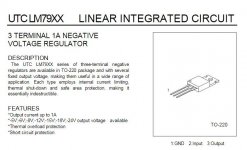
As mentioned before regulator 7924CT gets hot, I do not have experience to say if it is too much.
What else?
Last edited:
I cleaned all the flux all over the board and inspected for whiskers. It seems that all is OK. I do not have experience to tell which ones are "cold but redid some of the joints especially at the regulators.A couple of things:
You seem to be leaking voltage between the PSU and the preamp boards. I don't believe you should be dropping a volt on the positive side and you really shouldn't be dropping the 3 volts on the negative side.
What is the voltage at the output XLR pins of your supply? Remember -- COM on the meter should be applied to the GROUND (the colour of the wire doesn't matter but black is the convention) and the voltages taken in reference to that common ground basis.
More importantly, I think you probably need to examine your solder joints. A lot of them look "cold" to me. And it's hard to tell, but there might be whiskers of solder between pads. There is certainly flux that ought to be cleaned off. That might be the problem.
Hope this helps.
The voltage at PSU unit w/o load is +/- 31.8V.
I inspected the board carefully with a lens both side but could not find anything.
I still have the voltage drop.
It drives me crazy because my wife keeps telling me to buy a preamp to start using the new turntable 🙂
Attachments
Last edited:
shomescu,
I think you misunderstood me. Please measure the voltage across the resistors I mentioned. So one probe on one end of a resistor and the other probe on the other end. This measures a voltage drop which allows us to infer the current flow. Can you please do that for R30-R33? Since you feel the U2 7924 regular is running very hot, it is important to measure the current there.
Also do the same for R25, R28, R29.
With COM probe at GND, please measure the voltages at the input and output pins of U2.
No they are not. I have followed the directions from the forum (post # 1862) and used no insulation......are the regulators isolated against the heat sinks?
Sorry Dennis, I understood wrong, my lack of experience...shomescu,
I think you misunderstood me. Please measure the voltage across the resistors I mentioned. So one probe on one end of a resistor and the other probe on the other end. This measures a voltage drop which allows us to infer the current flow. Can you please do that for R30-R33? Since you feel the U2 7924 regular is running very hot, it is important to measure the current there.
Also do the same for R25, R28, R29.
With COM probe at GND, please measure the voltages at the input and output pins of U2.
Measured as explained:
R30 = 1.60 V
R31 = 0.09 V
R32 = 1.60 V
R33 = 0.09 V
R25 = 23.3 V
R28 = 1.19 V
R29 = 1.19 V
Also with COM on GND I got at U2:
- pin2 (middle) which is input = -25.6 V
- pin 3 which is output = -25.1 V
Ummm... isn't the input on a 7924 Pin 1?
While you've got your meter out maybe you could set it to measure resistance and with the power off check the solder joints by measuring from lead to lead, components that are supposed to be connected. The resistance should be under and ohm.
Bad/cold solder can be hard to identify visually but if you google it you should see some examples . But the meter should tell the tale.
Very interesting. Assuming your resistor values are correct, your R31/R33 measurement shows about 18mA current, which is consistent with your R28/R29/R25 measurements. But your R30/R32 measurements imply 320mA flowing through them.
Please verify that you have 10ohm resistors at R30-R33.
Do you have a CRC power supply upstream? If so, can you just hook up just this channel and measure the voltage across the 'R' as a sanity check and indicate what the value of R is?
If all these check out then between the parts C23/C25/C26/U2 there is a current leak. Given you comment about a hot 7924, U2 is the more probably suspect.
Edit: Please check your solder joints first as mhenschel suggested.
Edit2: Pin 1 is ground, Pin 2 is input, Pin 3 is output.
Attachments
Last edited:
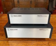
I have completed my Pearl 2 build and wanted to report on my experience. First, I want to thank those of you here who helped me out along the way. This thread is an amazing resource. I marvel at how generous people are with their time and experience.
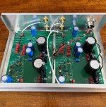
Most of my components came from Mouser. I have attached a copy of the invoice/parts list in case anyone is interested. It is an amalgamation of the original list from the build guide, and other lists I found here and elsewhere. You will need to double check quantities, since I had some components already on hand, and ordered extra of some for use on other projects. I substituted BC550 diodes for the ZTX450 diodes in the original specs because I could not find the ZTX450s in stock anywhere. The BC550s work fine so long as you note the correct pin orientation.
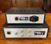
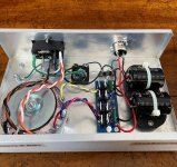
I used a Hammond 1182J22 transformer that I purchased from Mouser. It has roughly the same specs as the Antek transformer referenced in 6L6's original post. It is more expensive. However, I could not find the Antek in stock anywhere. For the PSU, I used a Peter Daniel rectifier board very similar to the one used by 6L6. I ordered it here: https://audiosector.com/product/single-rectifier-pcb. The cases came from eBay. They were inexpensive as these things go (I believe I paid around $75 for the two), and I think they look just fine. The combination IEC receptacle, switch, and fuse unit came from Amazon. The knurled nut for the turntable ground came from a local hardware store.
I have only listened to my Pearl 2 for several hours so far. However, I am already extremely pleased with it. My system includes an AR XA turntable, run through a Hegel H80 integrated amplifier, and played through Frazier Concerto speakers (a weird combination of old and new). I value the Hegel's clarity and great DAC. However, it leans towards the bright (at least to my ears), especially with digital sources. The Pearl 2 provides a rich, full sound, with a big low end. It's great. I could not be more pleased.
Most of my components came from Mouser. I have attached a copy of the invoice/parts list in case anyone is interested. It is an amalgamation of the original list from the build guide, and other lists I found here and elsewhere. You will need to double check quantities, since I had some components already on hand, and ordered extra of some for use on other projects. I substituted BC550 diodes for the ZTX450 diodes in the original specs because I could not find the ZTX450s in stock anywhere. The BC550s work fine so long as you note the correct pin orientation.
I used a Hammond 1182J22 transformer that I purchased from Mouser. It has roughly the same specs as the Antek transformer referenced in 6L6's original post. It is more expensive. However, I could not find the Antek in stock anywhere. For the PSU, I used a Peter Daniel rectifier board very similar to the one used by 6L6. I ordered it here: https://audiosector.com/product/single-rectifier-pcb. The cases came from eBay. They were inexpensive as these things go (I believe I paid around $75 for the two), and I think they look just fine. The combination IEC receptacle, switch, and fuse unit came from Amazon. The knurled nut for the turntable ground came from a local hardware store.
I have only listened to my Pearl 2 for several hours so far. However, I am already extremely pleased with it. My system includes an AR XA turntable, run through a Hegel H80 integrated amplifier, and played through Frazier Concerto speakers (a weird combination of old and new). I value the Hegel's clarity and great DAC. However, it leans towards the bright (at least to my ears), especially with digital sources. The Pearl 2 provides a rich, full sound, with a big low end. It's great. I could not be more pleased.
Attachments
flip69, It's great that your Pearl 2 is up and running and you are enjoying the music.
One more thought: the wire from IEC ground should go directly to the chassis connection and bolted down with a lock washer and nut. The wire from the circuit ground lift bridge can then be connected to the chassis ground on top of the safety ground wire, held in place with another lock washer and nut. The intent is that the chassis safety ground is not disturbed and remains in place regardless of other work that may be done within the chassis.
One more thought: the wire from IEC ground should go directly to the chassis connection and bolted down with a lock washer and nut. The wire from the circuit ground lift bridge can then be connected to the chassis ground on top of the safety ground wire, held in place with another lock washer and nut. The intent is that the chassis safety ground is not disturbed and remains in place regardless of other work that may be done within the chassis.
- Home
- Amplifiers
- Pass Labs
- Building a Pearl 2