That won't, unfortunately, deactivate the output stage. It deactivates one stage of gain. Base current thru the predriver will still be amplified - just not by anywhere near as much. Will it protect anything? Maybe. The gain reduction would certainly reduce the amount of current available to a low impedance load. But maybe not enough to prevent overdissipation in all situations.
One suggestion would be to deactivate the VAS. This can be accomplished by shorting base to emitter on both halves of the VAS. Both the active device and the current source on single ended designs and both actives on symmetric ones like the Leach. QSC does this on their PLX series amps.
OK boys...
Things have slowed down and now expecting 40hr weeks ( thank god )
Now...
I'm gonna spend some time working on the amp again.
i have to figure out a way to implement a simple "protection circuit for the output devices but for now i need to finish the power supply and then deal with the rest latter on.
For the power supply I remembered a few members said to stay away from fast recovery rectifiers, so...
Here's what I'm looking ( just remember i want to be able to "weld" with this sucker ! ) at Vishay 8AF, Vishay 1N1183, Vishay 93513.
Those are the final candidates.
Caps are on order from my supplier ( 20 x 10000uF @ 1ooVDC ).
He also found my transformers as well at a very good price !
they are isolation toroidals rated for 1.5KVA dual primaries and dual secondaries, this will allow me to run lower voltage in the secondaries as i will hook up the primaries in series giving me a 2:1 ratio with a secondary voltage ~60VAC.
Hi,
wiring the primaries in series and feeding them with half the intended mains voltage will (roughly) half you transformer rating from 1500VA to ~750VA.
wiring the primaries in series and feeding them with half the intended mains voltage will (roughly) half you transformer rating from 1500VA to ~750VA.
Adrculda said:
Here's what I'm looking ( just remember i want to be able to "weld" with this sucker ! ) at Vishay 8AF, Vishay 1N1183, Vishay 93513.
Those are the final candidates.
If you're going to bother with stud diodes, use the 60 or 70 amp ones (Think DO-5 not DO-4). The 35 amp units don't have much better surge ratings than a $5 50A full wave block. Paralleling those isn't out of the question, either. And remember that stud diodes are hot on one terminal which complicates the heat sinking.
back at it again...
finishing up with my last "project" made me wanna try and get this one rolling and finished before Christmas !!
Still deciding on a bunch of different things, but will be wrapped around 2 1.5KVA toroids with dual 55V secondaries with dual 50A bridge rectifiers on each power supply and 10 x 8200uF 80V caps on each supply. Also there's a soft start board in the works with a triple 12V feeds rated 7.5A each and a 5V rated at 5A. One of the 12V and the 5V will be regulated as meanwhile the other two will used to feed the pre-drivers at 67V.
all there's left to do is figgure out what drivers i want to use as TO3's have a limited mounting options, where as the TO3P or TO267 can be easily mounted to any flat surface and handle the same amount of power as the TO3 Package.
Now...
what are you guys using in your amps and why is the question 😎
Now...
what are you guys using in your amps and why is the question 😎
Depends on what kind of heat sink you can get and how much trouble you're willing to go through to build the PCB. Flat-on-one-side heat sinks with no place for a row of TO-3's are the most commonly available if you're doing this on the cheap. In that case, TO-247's are best - even beating out TO-3's thermally when the TO-3's have to be mounted using angle aluminum instead of directly.
I have to be honest...
i think im getting lazy as im very inclined on suing high power OP-Amps to drive the output stage as it simplifies things a lot and offer thermal protection ( on some models ) and pretty good slew rates for a decent price and not ony that but simplifies the build.
Currently looking at OPA541 or LM675.
Also im more and more inclined to use a regulated power supply.
Whats your guys input on this one....
If you want a regulated supply I sure as heck hope you mean switch mode. Otherwise, it's just a lot of expensive waste heat. Of course if just the opamp supply is regulated - that's expected.
About using a power opamp to directly drive an OPS - that would let you do a high performance QSC-type circuit. Driving a simple CFP stage in trans-nova with a 5532 doesn't really have enough oomph to run 2 ohms cleanly. Crank up the supply voltage enough and you run out of beta before you run out of toroid and capacitor. With a beefy op amp, you'd stand a chance. If it were also high speed that's even better.
Some time ago, I got hold of some AD815's in the 15-pin TO-220 for a song. Half an amp output current, current-mode-feedback input stage. That would drive the heck out of a QSC output stage.
The 675 may or may not work - if you use a voltage feedback opamp, conventional wisdom is to use one that is unity gain stable.
The way i would set it up is with 2 op-amps, 1 running normally and invert th other with feedback on both and there still would be a driver in the picture. The reason why I'm inclined to use it is because it would simplify a lot of the input and biasing circuitry and both units offer overheating protection.
What are some good high power OP-AMP's that are floating around out there ??
I dont mind spending upwards of $40/ea. Op-amp .
will post a quick "doodle" up latter on tonight after im done with the tie rod end on this A4.
What are some good high power OP-AMP's that are floating around out there ??
I dont mind spending upwards of $40/ea. Op-amp .
will post a quick "doodle" up latter on tonight after im done with the tie rod end on this A4.
The reason why I'm inclined to use it is because it would simplify a lot of the input and biasing circuitry and both units offer overheating protection.
Overheating/overload protection in the op amp doesn't necessarily translate to the same for the whole amp.
Overheating/overload protection in the op amp doesn't necessarily translate to the same for the whole amp.
If its mounted centrally on the main sink it will 😎
If its mounted centrally on the main sink it will 😎
No. The thermal protection in the IC responds to junction temperature, not case temperature. If the dissipation in the IC is relatively low (which it will be compared to hard service), Tc will never get hot enough to shut the IC down. Until long after it's too late for your output transistor bank.
No. The thermal protection in the IC responds to junction temperature, not case temperature. If the dissipation in the IC is relatively low (which it will be compared to hard service), Tc will never get hot enough to shut the IC down. Until long after it's too late for your output transistor bank.
Shitty, still i wouldn't worry about it as the heat sink is forced cooled by a 120mm Fan and can be set up for push pull configuration if needed, but always can build a small thermal management board with a PWM setup to control 2 fans.

Trouble with the amp.
I did in fact build the amplifier for the posted schematic,
I'm now having a problem getting the power supply voltage up to full voltage.
If I make the power supply voltage at lets say, 55VDC peak to peak it works well. However, when I go above that voltage, the power supply gets a huge inrush of current and pops the fuses!
I'm trying to run this at 120 a channel (240 vDC across the rails)
What is amiss here? It will play nicely at lower than those voltages.
Thanks for any help you can provide,
Robert
What outputs (build details) ?? , most are 230Vce -some 250.
120V is pushing this rating. This type amp I would not push 90V rails.
A class h stepper would be better at >100V Vce is split over 2 devices.
Project 117 would not be good with modern devices without some sort
of decoupling at the pre-drivers. There are many other "refinements" that
I could not live without for class AB amps >500W.
OS
Trouble with the amp.
Thanks for the reply,
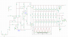
I have attached my Tina 10 build where I did model it before the build took place.
The plan was to use 150 VDC rails on this amplifier, but I decided that would really be pushing it, so I settled on 120 VDC per rail +/- 120 VDC.
Outputs are MJL2193/94 to-3 types and there are 20 in total, the transformer in use is a 4kva torrid with 220 VAC primary and 200 VAC center-tapped secondary. one thing to note is that I swapped out the BD139 and used an MJE340 in it's place.
I tried to attach the actual Tina 10 file to this reply, but it states it is an invalid format. So I attached an .PNG shot of it instead.
As you stated on your reply, there is no Pre-driver DE-coupling used in the amp. I will add some in there and see if it helps with the problem.
Robert
Thanks for the reply,
I have attached my Tina 10 build where I did model it before the build took place.
The plan was to use 150 VDC rails on this amplifier, but I decided that would really be pushing it, so I settled on 120 VDC per rail +/- 120 VDC.
Outputs are MJL2193/94 to-3 types and there are 20 in total, the transformer in use is a 4kva torrid with 220 VAC primary and 200 VAC center-tapped secondary. one thing to note is that I swapped out the BD139 and used an MJE340 in it's place.
I tried to attach the actual Tina 10 file to this reply, but it states it is an invalid format. So I attached an .PNG shot of it instead.
As you stated on your reply, there is no Pre-driver DE-coupling used in the amp. I will add some in there and see if it helps with the problem.
Robert
Attachments
- Status
- Not open for further replies.
- Home
- Amplifiers
- Solid State
- Building a Monster... Class A