no. I've read Self's reproducing a signal to maximise current demand.
I don't know what doubled full Power square wave you are referring to but it doesn't sound like a valid music signal to me either.
And you already know my views on undersizing the smoothing.
I don't know what doubled full Power square wave you are referring to but it doesn't sound like a valid music signal to me either.
And you already know my views on undersizing the smoothing.
I just read the section titled "Enhanced loudspeaker currents" in his famous amplifier design book (page 220 in the one available online from my library) and it's exactly the same effect. Is this it or is it something else he has written you are referring to?
I agree with his conclusions in the end of this section:
But if you still want to design the amplifier to allow these it still won't be an issue for the power supply. If the power supply capacitors are big enough (which I know yours are!) then the power supply will only care about average current draw over these timescales - which is often even lower with reactive loads than resistive.
I do not believe it is reasonable to expect a these very high powered amps to be able to deliver these currents though. If you are, then almost all commercial amps for this application in existence would be bad.
Power supply capacitance is important though. Too little and clipping will not be very nice...
I agree with his conclusions in the end of this section:
1 Music signals do not contain high-level rectangular waveforms, nor trapezoidal approximations to them. A useful investigation would be a statistical evaluation of how often (if ever) waveforms giving significant peak current enhancement occur. As an informal test, I spent some time staring at a digital scope connected to general-purpose rock music, and saw nothing resembling the test waveform. Whether the asymmetrical timings were present is not easy to say; however, the large-amplitude vertical edges were definitely not.
2 If an amplifier does not have a huge current-peak capability, then the overload protection circuitry will hopefully operate. If this is of a nonlatching type that works cleanly, the only result will be rare and very brief periods of clipping distortion when the loudspeaker encounters a particularly unlucky waveform. Such infrequent transient distortion is known to be inaudible and this may explain why the current enhancement effect has attracted relatively little attention so far.
But if you still want to design the amplifier to allow these it still won't be an issue for the power supply. If the power supply capacitors are big enough (which I know yours are!) then the power supply will only care about average current draw over these timescales - which is often even lower with reactive loads than resistive.
I do not believe it is reasonable to expect a these very high powered amps to be able to deliver these currents though. If you are, then almost all commercial amps for this application in existence would be bad.
Power supply capacitance is important though. Too little and clipping will not be very nice...
What I try to do is build amps that are as well behaved at 2 ohms (that is, two paralleled cabs, bridged) as most store bought "pro" amps are when driving 4 ohms stereo. It's not that hard - you just have to put in those few extra dollars that the bean counters want to save, and it weighs 10 pounds more. It's either that or BUY two amps for every one that you "need" - which ends up weighing more and costing more.
What I've found that it takes is about 50% more VA capacity in the trafo to run 1/8 power 2 ohms indefinitley, or 1/3 at 4 indefinitely (strictly to prevent overheating - I design for the same drop under load), double the typical SOA to allow 1.5 ohms resistive and 4 ohms fully reactive at unloaded supply voltage before limiting, three stages of current gain in the followers - which many amps do NOT have, and 20,000 uF per rail of cap. (1977 CS800 has only 10k, RMX5050 has only 8k).
It amounts to a different set of design trade-offs than either the audiophile world or the pro amp makers are willing to make.

To wg_ski
What sort of limiter are you using?Does it sense the output level or line level signals.
What sort of limiter are you using?Does it sense the output level or line level signals.
The limiter senses loss of feedback (slewing) on the op amp front end of the power board. To test it separately, I hooked up the back to back zeners and sense resistor directly off the preamp output.
danieljw said:nice work chief
Thanks for the encouragement. With stuff like this, the circuits are the easy part. The hard part is figuring out how it all fits together (and I'm not a manufacturing guy or mechanical engineer or own a machine shop).
Adrculda,
I'm not sure where you currently stand on building your monster amp, but if it is still in the works I may have a few decent transformers for you. 2Ea x 1.5kVA medical isolation transformers, 120V:120V. Hook up the primaries in parallel and the secondaries in series and you will have +-120Vac, rectified = +-170VDC. With these rails into a 4 ohm load, you should achieve ~3,600Wrms (more than the kVA rating of the transformers). So if you really want to go nuts and have a 4ohm stable amp, you could use 4 of these transformers (in a series/parallel configuration), creating a 6kVA transformer.
I'm not sure where you currently stand on building your monster amp, but if it is still in the works I may have a few decent transformers for you. 2Ea x 1.5kVA medical isolation transformers, 120V:120V. Hook up the primaries in parallel and the secondaries in series and you will have +-120Vac, rectified = +-170VDC. With these rails into a 4 ohm load, you should achieve ~3,600Wrms (more than the kVA rating of the transformers). So if you really want to go nuts and have a 4ohm stable amp, you could use 4 of these transformers (in a series/parallel configuration), creating a 6kVA transformer.
Adrculda,
Rod Elliot's small amount of information on this amp leads me to believe there will be some very steep obstacles to overcome in the 1.5kw arena. What special steps are you providing in this build to prevent oscillation of the 30 plus output devices? Are you going to bandwidth limit the frontend for bass/mid use or do this with your PA equalizer.
I had thought hard on building one of these -- just to do it. However, my knowledge to this point would not have been adequate.
Please let us know if you ever plan on a GB of you pcb's. After your beta trials. I have tons of aluminum and some really nice HUGE isolation trannies just ready for this project.
Many kudos for giving this thing a go.
Tad
HI All..
its been a while since i poked my head around here...
the project is moving along as fast as molasses in -30 weather.
Summer season swung around and i got stupid busy in the shop maintaining and getting a whole bunch of cars ready for the track season. Been working 70+ hr weeks and haven't spent too much time on the project lately.
the 2 Main Power supply boards are done and almost have all the caps in place and the main supply bridging board is done.
Will get the wife to take some pics and post them up.
I Still need to figure out a way to protect the output in case that the and goes into oscilation.
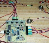
wg_ski said:And a front end PCB - working on a test jig. Balanced inputs, bridge mode switching, limiters, and temp sensors (the BD139's at the top, which will attach to the heat sinks).
Hey wg_ski
Looking good !!!
Hows that board holding together ???
Adrculda said:HI All..
its been a while since i poked my head around here...
the project is moving along as fast as molasses in -30 weather.
We warned ya. 😉 It really does take that long. I found that you can work on it intensely for a couple weeks, and then you have to walk away for a while. But don't stop - eventually it will get done.
Mine are progressing - slowly. All the wiring harnesses for all 4 are done, all 4 front end boards tested, and all 8 power PCBs stuffed except for the TO-247's and 264's. One has the outputs,commutators and heat sinks installed, but I haven't begun test and debug yet. Looking for a 4 or 5 day uninterrupted window before starting that - because you know it never works perfectly the first time and you can't put it down till it does.
I ended up with one design flaw so far - the overtemp muting circuit had minor problems that required adding a resistor to -15V to make sure the clamp was hard turned off when it's not supposed to be clamping. Just reducing the base drive to zero was not enough if the input signal is much above 5V peak.
I Still need to figure out a way to protect the output in case that the and goes into oscilation.
Most amps don't have any protection for that per se- you just have to design so that it won't go unstable in normal operation. Short level-dependent bursts of oscillation could still happen, but are not catastrophic. That's not the same as a completely unstable output stage that will go into cross conduction and self-destruct. That would happen without drive or even a load. Protection against that is the light-bulb limiter while you're debugging - and it's pretty much the only thing that works if the amp does that. The input should be filtered to prevent HF overdrive, but that's easy.You could even disconnect the speaker (and zobel) in the presence of excessive HF.
The Crimson (Crimson Elektrik) range of power amps have an HF detector added to the VAS, this triggered a discrete Thyristor which in turn starved the tail currents of both the LTP and VAS stages.
It latched off until reset.
It latched off until reset.
Yes, filter the input.wg_ski said:The input should be filtered to prevent HF overdrive, but that's easy.You could even disconnect the speaker (and zobel) in the presence of excessive HF.
Yes disconnect the speaker.
Do not disconnect the Zobel.
The Zobel or Thiele Network is/are the HF load that helps prevent oscillation.
AndrewT said:Yes, filter the input.
Yes disconnect the speaker.
Do not disconnect the Zobel.
The Zobel or Thiele Network is/are the HF load that helps prevent oscillation.
The zobel prevents oscillation associated with inductive loads (like speakers at high frequency). Disconnect the speaker, and you don't need the zobel.
If you put excessive HF into a zobel - like a nice continuous 20 KHz sine wave, the resistor will burn up. You want it disconnected if you detect something like this.
Hi,
an inductive load increases the stability margin. This makes oscillation less likely.
Removing that load and leaving the output open circuit could promote oscillation. That's why the Zobel should stay in circuit to give a load that is effective at high frequency.
an inductive load increases the stability margin. This makes oscillation less likely.
Removing that load and leaving the output open circuit could promote oscillation. That's why the Zobel should stay in circuit to give a load that is effective at high frequency.
AndrewT said:The Crimson (Crimson Elektrik) range of power amps have an HF detector added to the VAS, this triggered a discrete Thyristor which in turn starved the tail currents of both the LTP and VAS stages.
It latched off until reset.
That sounds pretty simple to implement.
Also another way of doing it is cutting signal to pre-drivers by cutting power to them using a small relay as this wouldn't be in signal path and therefor no deterioration would occur. This could also serve as a "soft" start with using either a timer circuit or a voltage gate using some zener diodes only allowing them to receive power only at a specified voltage.
now if there was a way to keep them latched in open so the amp had to be reset then you would be golden as it work perfectly as a "protection circuit" for very low loads as if rail voltage dips below the specified limit if would cut the power feed to the pre-drivers and this would render all output devices in-operational.
I will see if i can draw it up as a picture is worth a 1000 words.
Here's a quick sketch...
The relays can be used to trigger and cut power to the driver section when tripped from either thermal or the feedback protection circuit to prevent it from going into oscillation and self destruct.
An externally hosted image should be here but it was not working when we last tested it.
The relays can be used to trigger and cut power to the driver section when tripped from either thermal or the feedback protection circuit to prevent it from going into oscillation and self destruct.
- Status
- Not open for further replies.
- Home
- Amplifiers
- Solid State
- Building a Monster... Class A