Well, my original technique I was going to use to stretch the mylar is not going to work out as I had planned, so had to figure something else out that I will try today... pics soon..
I found this video clip today and thought it should be in this thread.
Martin-Logan repair on stretching and lifting jig. Showing glueing and stretching procedure. - YouTube
It's from a '.de' site and clearly shows tension being applied in both the vertical and horizontal, hmm...
Any of you guys feel like commenting on the video?
Cheers..
Last edited:
Hi,
yes, horizontal tension is required too, but just so much as to iron out wrinkles and to smoothen the surface of the film.
jauu
Calvin
yes, horizontal tension is required too, but just so much as to iron out wrinkles and to smoothen the surface of the film.
jauu
Calvin
Thanks Calvin.
Yea, I knew that a slight tension had to be applied to the horizontal to get rid of the wrinkles, but it looks like he's applying quite a bit, doesn't it?
Yea, I knew that a slight tension had to be applied to the horizontal to get rid of the wrinkles, but it looks like he's applying quite a bit, doesn't it?
I ended up having to use tape at the sides to remove wrinkles, just like that last video clip I posted.
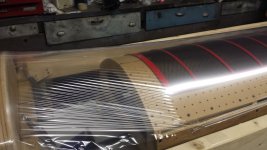
No success yet, as we ended up breaking the Mylar with the last turn of the stretcher. Luckily, I have another 100 feet of it left, and will atempt again tomorrow.
Here are a few pictures before we broke it:
No success yet, as we ended up breaking the Mylar with the last turn of the stretcher. Luckily, I have another 100 feet of it left, and will atempt again tomorrow.
Here are a few pictures before we broke it:
Attachments
Very Cool!!!
One last turn might not deserve another!!!! 😉
Remember, Any slight leftover wrinkles can be taken out with a little heat. 🙂
jer 🙂
One last turn might not deserve another!!!! 😉
Remember, Any slight leftover wrinkles can be taken out with a little heat. 🙂
jer 🙂
Hi,
one can't avoid a slight bow in the film's shape, but the amount of hour glass like curvature as in the pic is at least on the edge to too much.
I assume that the Mylar ripped from one of the outer edges, from the glue joint of the last strip of tape?
Typically You won't rip the film by stretching, as it takes considerable amounts of force before breaking.
First comes a phase of stretching which lasts until a elongation of ~3-4% is reached.
Above that the flow-phase begins, where the required stretching force actually sinks a bit again.
Breakdown occurs at some 10-15% of elongation iirc.
It are the shearing forces, due to stress on the film at the tape glue joints that finally rip the film apart.
jauu
Calvin
Very Cool!!!
One last turn might not deserve another!!!! 😉
Remember, Any slight leftover wrinkles can be taken out with a little heat. 🙂
jer 🙂
Thanks jer. Haha, yea we tweaked it just a little too much, but like I said, I have 100' of the stuff leftover. 😛
I'm assuming that you mean we should apply heat before it makes contact with the VHB tape (?)
Hi,
one can't avoid a slight bow in the film's shape, but the amount of hour glass like curvature as in the pic is at least on the edge to too much.
I assume that the Mylar ripped from one of the outer edges, from the glue joint of the last strip of tape?
Typically You won't rip the film by stretching, as it takes considerable amounts of force before breaking.
First comes a phase of stretching which lasts until a elongation of ~3-4% is reached.
Above that the flow-phase begins, where the required stretching force actually sinks a bit again.
Breakdown occurs at some 10-15% of elongation iirc.
It are the shearing forces, due to stress on the film at the tape glue joints that finally rip the film apart.
jauu
Calvin
Thanks for this information Calvin, very useful for the next attempt.
To be honest, I really didn't look at the break that close as to pinpoint what caused it to rip. ( I was too angry..😡
 )
)I want to achieve a resonant frequency of 100-200 Hz and not much higher than that.
With small amounts of tension applied to the horizontal, do you think that a 2% vertical elongation would be enough?
The jig is 96 inches from arch to arch, so for a target of 2%, I need to stretch just under 2 inches and I was beyond that.
Any further comments or suggestions are welcome..🙂
P.S. I got your PM, thanks again. 😉
____________________________________
For anyone following the thread, I'm going to have to wait before the next attempt as there needs to be more than me and one other person to do this, that's one other lesson I learned from this first attempt.
cheers
-wreck
Apply heat if needed after it is mounted.
Also heating will add more some more tension as well.
So you only need enough mechanical to keep the large wrinkles out.
Although I am no expert when it comes to mechanical tensioning.
I get about 70Hz to 110Hz with my 3" to 4" wide panels using just heat with only a slight taught of the Mylar as it is mounted, Just enough to make it wrinkle free on a piece of glass.
Typically you will get aprox. half that frequency when you Double the width to 8" or so.
I hope that helps. 😉
jer 🙂
Last edited:
You don't have to tension your diaphragm so much. Just enough to get rid of wrinkles is good enough, IMO.
Wachara C.
Wachara C.
Hi,
besides the pure mechanical tension, the base resonance of the stretched film is defined by the shortest dimension.
With curved panels this is typically the distance between the horizontal spacers (~70-100mm).
Following roughly the 70:1 d/s rule and for a d/s value between 1.0 to 1.5mm and a elongation of ~1.5% (2% max):
The thinner the film the less mechanical tension is possible, hence lower Fs.
With thicker films higher tension and as such higher Fs is possible.
Using 3.5-6µm films You´ll end up between 120Hz to 180Hz.
12µm film as used e.g. in MLs Prodigy may reach up to 250Hz.
Keep in mind that most films cannot hold the tension longtime, but will soften a bit and the Fs sinks and settles at its final value over app. a 1/2 year period.
This happens almost always when the membrane is only tensioned mechanically, as is the case with MLs curved panles.
Fs reduction over settling period may reach up to -20%.
If the membrane is tempered it almost instantely settles very close to its final values (pre-ageing).
While this is feasable with flat panles, curved panles require a film with certain special properties, as tempering the ´normal´ film candidates will result in that known hour-glass shape (afaik this film-type is obsolete since years and I assume I´m the one who got the last supply of it 😛 )
jauu
Calvin
Many thanks to all of you guys, you tend to make this much easier then once thought, and that's a good thing! 🙂
Stay tuned...
-wreck
Stay tuned...
-
wreckWell I finally got enough helpers to get a stretch and set done.
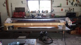
This time I used around 1.75% elongation (vertical) for fear I'd break the Mylar again. So far it looks and feels like a good set, but only completion and testing will reveal that. My crew had enough by the time we got this done, so the next step for one panel completion will be a few days. I have my fingers crossed...

I snapped a pic for you all, here you go:

I do, however, have a question or three...
What is the best method for attaching a wire to the copper ring I need to install? And does the Licron crystal need to be applied all the way to the copper ring? Does it differ depending if the copper ring has conductive adhesive?
Cheers all...
This time I used around 1.75% elongation (vertical) for fear I'd break the Mylar again. So far it looks and feels like a good set, but only completion and testing will reveal that. My crew had enough by the time we got this done, so the next step for one panel completion will be a few days. I have my fingers crossed...
I snapped a pic for you all, here you go:
I do, however, have a question or three...
What is the best method for attaching a wire to the copper ring I need to install? And does the Licron crystal need to be applied all the way to the copper ring? Does it differ depending if the copper ring has conductive adhesive?
Cheers all...
Looks great!!! 🙂
Yes you need to have the licron coating contacting your charge strip or else it will not charge!! 😉
If the adhesive on the tape is conductive then it will most likely be Okay to lay it on top of the coating.
But don't quote me on that as I have never used and tested a material as such.
I have always made sure that the metal side was touching the coating.
For a connection you can either have a small tab of the copper tape sticking out and connect to that.
Or, you can use a small gauge stranded wire lightly tacked on to the copper strip with a small amount of solder before you sandwich the Two halves together.
Even a small piece of some magnet wire will do.
Or, even a piece of 30ga. Kynar coated wire wrap wire will suffice and probably be better.
I have tested such wire and its insulation is capable of withholding close to 10Kv without arcing through!!!
You only need enough solder lightly tin the wire and copper tape to make it stick, where ever you decide to place it.
Just a simple quick tack is all you need.
jer 🙂
Thanks, and thanks for jarring my memory, I should have looked it up, but I was being lazy, and well...celebrating..haha..
Hi,
looking well, and I don´t intend to spoil the fun, but next time try even less horizontal stretch. 😉
The light reflexes show that some hour-glass deformation of the diaphragm is still present, even looking right on the edge of Fail for the couple of middle segments.
Good news though, it seems to be within the Pass-band.
For coating, try to only coat the free vibrating segment area, leaving a couple of mm free rim to the spacers. Then ´paint´ one or two fingers from each segment to the copper strip. Use a bit more coating, for lower resistance and really ´spill´ it over the copper strip.
Besides oxidization of the copper, only the very thin rim of the copper strip is effective in contacting and this is prone to lowlevel arcing.
Think about ´bridging´ the gap for example using cellulose strips. 😉
jauu
Calvin
Gee, I must remind myself not to tell the secret secrets
Wreck: The conductive side of the copper tape can be placed directly on the licron. Works most excellently! In fact, it is much easier than using non-conductive tape: easier to lay out the conductive tape because it stays in place. AMHIK. Your stator looks excellent: did you wrap the DS tape around the edges per Charlie M's Jazzman procedure? If not, you need to get the other stator in place ASAP. I had trouble with my DS tape pulling away from the edges because I didn't wrap the edges...Good luck!
Gee, I must remind myself not to tell the secret secrets
Hey now... I'd tell you my secret secrets...(if I had any...
)Thanks for all the compliments guys... And the advice on the charging ring is duly noted..😉
I know there is some hourglass effect within the cells, but if you recall, I actually planned for that with the thickness of the spacers being .090" on the back stator, and only .060 on the front.
That being said, there are a few cells towards the middle that are closer than I am comfortable with.
Do you guys think that a dot of silicone in the center of these cells would be of any benefit? (I'm not overly concerned about appearance, and would rather not tear the panel apart if I don't need to) ...Comments very welcome 🙂
I think what I'm going top do is put these things together 'as-is' and then address any problem later. That is, unless someone has a better idea.
Cheers
-wreck
- Status
- Not open for further replies.
- Home
- Loudspeakers
- Planars & Exotics
- Building a large curved ESL