It appears to be similar to the all in one where there are separate B+ runs per channel. So you need to figure out how many mA per channel per stage you will pull. Then select a resistor to drop the appropriate voltage at the operating point.
Say your first stage runs 10mA for example and you need to drop 20V. Your R then becomes 2000ohm.
Say your first stage runs 10mA for example and you need to drop 20V. Your R then becomes 2000ohm.
It appears to be similar to the all in one where there are separate B+ runs per channel. So you need to figure out how many mA per channel per stage you will pull. Then select a resistor to drop the appropriate voltage at the operating point.
Say your first stage runs 10mA for example and you need to drop 20V. Your R then becomes 2000ohm.
Hi,
1st stage Iq= 3.4mA (250V)
2nd stage Iq= 4mA (280V)
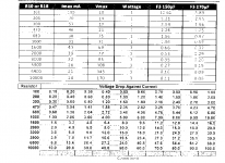
There is a resistor table in the manual that has Resistor Values, Voltage Drop Against Current and Current in mA.
Since I have +300V going into the board, then I need to drop 20V and then another 30V for 2nd stage?
The table shows for 4mA(2nd stage):
3.9K 15.6V drop
6.8K 27.2V drop
So I need something between 3.9K-6.8K to drop 20V?
For 1st stage, Iq is 3.4mA at 250V. I need to drop 30V for this?
The table shows for 3mA(1nd stage):
3.9K 11.7V drop
6.8K 20.4V drop
10K 30.0V drop
Do you know the equation to more accurately calculate the correct
R value for 3.4mA?
Thanks
Hi,
here is part of the table. Do you know what the values in the F3 150uF and 270uF are for?
there is no explanation in the manual. it's always nice to know what is going on.
I'm not sure thought for initial RC stage, don't you need to take into
account the current load of the 2nd stage as well? This is where I'm unclear.
thanks
Attachments
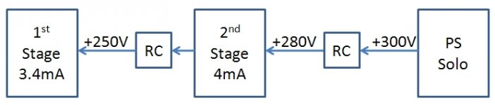
So assuming 12AX7's in both input and output positions and 300VB+
1. The output stage is drawing 5mA and is the first to encounter the B+ so following the chart for R18 @ 3Kohm you will drop 15V.
2. The input stage is drawing 1mA and lets assume is now 285V so following the chart for R10 @ 10Kohmn you will drop 10V so now the plate will see 275V.
If you run the tubes hotter then the voltage drops will be greater but what I have outlined above here seems reasonable. I would start there and take some measurements. From there you can fine tune by either increasing the R in the RC or reducing the cathode resistors to increase the current.
The F3 capacitors from what I understand affect the ripple/noise in the power supply at each stage in the RC filters. 150uF would be the standard here...this part starts to get a little over my head...
Last edited:
how do you get 5mA for output stage and 1mA for input stage?
I thought the Iq is the load current for each stage?
will try it later. need to order the parts first.
thanks
I thought the Iq is the load current for each stage?
will try it later. need to order the parts first.
thanks
From the curves it looks as though you would not select an operating point above 4ma for most applicaions. Looks like 1-3mA is the most applicable.

I have a question for the experts. If I want to run two transformers, For instance a seperate filament tranny, How would I wire that up? Do I need two seperate power inputs?
No, just wire the primaries of both transformers back to the one IEC inlet. Remember to fuse for both!!
No, just wire the primaries of both transformers back to the one IEC inlet. Remember to fuse for both!!
Thank you!! I have one of those IEC with a fuse. Would I have to add a seperate one? cheers!
Well, the really right way to do it is have the appropriate fuse for each transformer, but its OK to have just the one fuse - calculate the rating for both Tx
Some guys put a main fuse on the primary (like you have), and then separately fuse the supply to the amp after the transformer.
Fran
Some guys put a main fuse on the primary (like you have), and then separately fuse the supply to the amp after the transformer.
Fran
Well, the really right way to do it is have the appropriate fuse for each transformer, but its OK to have just the one fuse - calculate the rating for both Tx
Some guys put a main fuse on the primary (like you have), and then separately fuse the supply to the amp after the transformer.
Fran
Thank wood turner, I'll put in a secondary fuse to the filament just to be safe.
Cheers!!
What is the purpose of the fuse? If the fuse is sized to handle the cold start inrush current it can do nothing to protect the transformer under overload conditions. The bulk of the small transformers we use are fuses themselves. If they short or overload they will let out the smoke and fail open circuit with no harm done to the building. If you want overload protection a fuse will come up short.
DT
DT
The iec fuse will only protect against sudden large current draws - eg short to earth. It's the basic safety measure that must be implemented. Size it just above where it will never blow under normal operating conditions, or you could use a slow blow
...
What dualtriode says is correct - fusing the secondary side will better protect the components....
...
What dualtriode says is correct - fusing the secondary side will better protect the components....
The iec fuse will only protect against sudden large current draws - eg short to earth. It's the basic safety measure that must be implemented. Size it just above where it will never blow under normal operating conditions, or you could use a slow blow
...
What dualtriode says is correct - fusing the secondary side will better protect the components....
Thank you. I know the fuse I have in here right now is a 10a 250v which is common. I'm looking at toggle switches right now and trying figure out what range I can use. not too many 10a 250v toggles..
The iec fuse will only protect against sudden large current draws - eg short to earth. It's the basic safety measure that must be implemented. Size it just above where it will never blow under normal operating conditions, or you could use a slow blow
....
Normal operation includes the inrush current when you turn the thing on. If you also use an inrush limiter the size of the fuse can be reduced even further to provide some degree of equipment protection.
DT
Hey guy, my amp is up and running. Have one question. I have an unused CT on my Filament Tranny. Can or Should I ground it to star ground on the board? Thank and Happy Holidays!!!!
Hey guy, my amp is up and running. Have one question. I have an unused CT on my Filament Tranny. Can or Should I ground it to star ground on the board? Thank and Happy Holidays!!!!
I might try and reference 1/4 b+ with that center tap
- Home
- Amplifiers
- Tubes / Valves
- Building a Aikido preamplifier