Hi there,
If your tubes draw 2.4 amps through the heaters then you really need at least 50% more power from your tranny.
4 amps should be good which is what I have. You'll get a drop in voltage and 2.5 amps will just not cut it sorry to say. That 6.3 volts will drop and overheat the core.
So Tranny #1 will be good, also you've got more power in mAmps which always helps the soundstage.
Last edited:
Hi there,
If your tubes draw 2.4 amps through the heaters then you really need at least 50% more power from your tranny.
4 amps should be good which is what I have. You'll get a drop in voltage and 2.5 amps will just not cut it sorry to say.
So Tranny #1 will be good.
Ok. thank you. tranny 1 it is. Also the CT wire for the heaters goes to ground?
Also the CT wire for the heaters goes to ground?
I believe so, even though i haven't used a CT tranny before.
Can someone else confirm his CT question?
(been out of my eelctronics workshop for a while and don't recall)
IMO you will want to use #1 - just be cautious of your B+ - you will want to get it down to 300-325 max. You will obviously not be using the 5V winding.
I am using the octal all in one as the input stage to a MOSFET power stage amp (Moskido) and use the voltage doubler for the heaters and wire them in series pairs. This effectively draws half the current and is supposedly easier on the regulator. I am using a 550V@125mA X 6.3V@4A PT.
The 4 6sn7's will draw about 40mA.
What is the purpose of you amp? You may want to consider the 6SL7/6SN7 if it is a preamp - unless you are building a HPA...its a pretty sweet combination.
I would try it without connecting the CT for the heater winding.
just be cautious of your B+ - you will want to get it down to 300-325 max.
ah yes didn't see the high voltage. I have used a 200mA 275 Volt tranny with good results.
A tube rectifier will drops some volts if you need to do that.
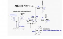
Really simple one from Bas and works well for a first build:
Attachments
Last edited:
IMO you will want to use #1 - just be cautious of your B+ - you will want to get it down to 300-325 max. You will obviously not be using the 5V winding. .
I think you might have the octal all in one without the shunt regulator? because mine needs three secondary windings.
I am using the octal all in one as the input stage to a MOSFET power stage amp (Moskido) and use the voltage doubler for the heaters and wire them in series pairs. This effectively draws half the current and is supposedly easier on the regulator. I am using a 550V@125mA X 6.3V@4A PT..
The 4 6sn7's will draw about 40mA.
What is the purpose of you amp? You may want to consider the 6SL7/6SN7 if it is a preamp - unless you are building a HPA...its a pretty sweet combination..
I'm going for a preamp. All I have is 6sn7 tubes right now. I have 16 of them. I don't have any 6SL7 tubes.
I would try it without connecting the CT for the heater winding.
Would that mean connecting it to ground or just tape it up?
Just tape it up...especially if you configure for voltage doubler you will not use the CT.
O.K Thanks. I was thinking about going Full wave. I still have alot of reading to do from The two books I recieved from Broskie. I guess these books will tell me how to bring down the B+ 300-325 max?
Yes, there are clues...You know that you will be pulling 40mA, and you can get your raw B+ without the tubes in the sockets. Assuming your electrolytics can handle the raw B+.
You can then calculate the resistor value to drop your B+...at least in the ballpark.
Say your raw B+ is 380V - you know you will be drawing 40mA - therefore to drop 80V you will need a resistor of approximately 2000 ohms...(80/0.040)...AND you know that you will be dissipating 3.2 watts so use at least a 5W resistor....
And you definitely want to do the voltage doubler and do heaters in series...works great and is easier on the hardware.
Last edited:
Say your raw B+ is 380V - you know you will be drawing 40mA - therefore to drop 80V you will need a resistor of approximately 2000 ohms...(80/0.040)...AND you know that you will be dissipating 3.2 watts so use at least a 5W resistor....
my experience is that the 2000 ohms resistor can be lower than that due to the losses in the transformer winding which causes more drops as more current is drawn....
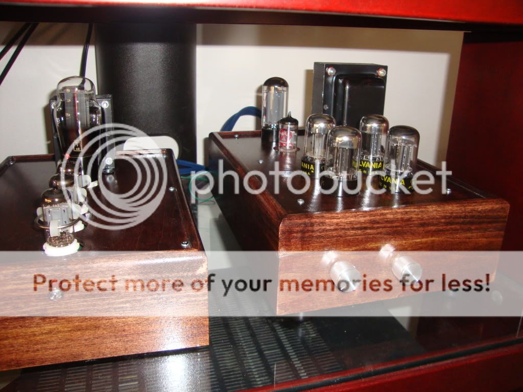
This is the preamp I had built recently, which has tube rectified and regulated power supply. The noise cancellation capacitor had been removed.
An externally hosted image should be here but it was not working when we last tested it.
An externally hosted image should be here but it was not working when we last tested it.
An externally hosted image should be here but it was not working when we last tested it.
Jim Hu
Hi Jim,
are those white covered caps polypropylenes? i used to get some from coffin who is a member here and also from Taiwan but nowadays i can't get hold of him....i need some caps, btw.....thanks
Yes, there are clues...You know that you will be pulling 40mA, and you can get your raw B+ without the tubes in the sockets. Assuming your electrolytics can handle the raw B+.
You can then calculate the resistor value to drop your B+...at least in the ballpark..
Say your raw B+ is 380V - you know you will be drawing 40mA - therefore to drop 80V you will need a resistor of approximately 2000 ohms...(80/0.040)...AND you know that you will be dissipating 3.2 watts so use at least a 5W resistor.....
o.K. I think its (R17) on my board. Right now I have a 1.5k resistor as recommended to start with by the typical parts value layout. Where do I measure the B+? I guess in the center pad B+ to G? aside of it is (H+/H-) where I can check the Heater voltage?
And you definitely want to do the voltage doubler and do heaters in series...works great and is easier on the hardware.
I see, so I want the voltage doubler. easiler on the iron and if I ever want to use 12.6 v tube, all I need to do is change the jumpers at the tube pins.
Last edited:
Yes, measure B+ from B+ terminal to G. Make sure to measure the heater voltage from H+/H- as the voltage is referenced to 1/4 B+. The H- will actually measure about 80V to G.
Yes, if you ever were to use 12V tubes it would just be a jumper change.
Again it would be some experimenting versus your actual wall voltage and other drops through the PSU resistors and caps but measuring the B+ without the tubes in will get you in the ballpark as to how much you need to drop to get to around 300V.
Yes, measure B+ from B+ terminal to G. Make sure to measure the heater voltage from H+/H- as the voltage is referenced to 1/4 B+. The H- will actually measure about 80V to G.
Yes, if you ever were to use 12V tubes it would just be a jumper change.
Again it would be some experimenting versus your actual wall voltage and other drops through the PSU resistors and caps but measuring the B+ without the tubes in will get you in the ballpark as to how much you need to drop to get to around 300V.
First off, Thank you so much for insight/help. Right now, my B+ its at 285V. I guess I have to order the right resistor. It sounds amazing right now 😀
Funny I just went back and did some readings...
My Raw B+ before the RC filter is 400V. The 6SL7 is pulling 1.3mA and the 6SN7 is pulling 10mA. The R in the RC filter is 6800 ohm. All the math adds up as I am dropping about 80V down to 320V B+ on the Aikido.
My Raw B+ before the RC filter is 400V. The 6SL7 is pulling 1.3mA and the 6SN7 is pulling 10mA. The R in the RC filter is 6800 ohm. All the math adds up as I am dropping about 80V down to 320V B+ on the Aikido.
nOOb heater PS question
Hi,
I have the Aikido Rev A all in one 9 pin board and I'm working on the heater power supply. I am using tubes that require 12.6v so I purchased a 6.3-0-6.3 transformer. I am a little confused by the wording in the Aikido manual. Are all four diodes to be used for the CT configuration, or only two? I interpreted the manual to say that all four are to be used (opposite of what the B+ section suggests for CT configuration...???) and two of the diodes get very warm very quickly (even on 50VAC from my variac) so surely, something is amiss. I have quadruple-checked all of my wiring and there are no errors other than perhaps erroneous assumptions about how things are supposed to be connected
Also, I believe the capacitors should be oriented such that no terminal contacts the un-used "AC" hole in the PCB for the transformer when used in non CT mode. Can someone please confirm?
Brian
Exactly what I needed. Thanks for the link!
PS-3 PSU
Have a look at the PS-3 manual since the All in one is simply a PS-3 with an aikido. It goes into depth on the 3 ways to wire up your heaters. Full wave bridge, full wave center tap, and voltage doubler.
Hi,
can someone help me out with the RC values for the Aikido Tetra Sans?
I'm using the PS-2 Solo set for 300V. For the Tetra Sans I'm using
both 12ax7 for both stages.
1st stage = +B 280V
2nd stage = +B 250V
There is an RC for each stage. So I just need to drop the 300V down
to 280V and then down to 250V There is a table in the manual but
it's confusing to me. It has current load values and resistor to use.
Do I add current loads of both stages to look up for the 1st stage RC values?
Tetra Phono All-in-One & Broskie Impedance Multiplier
I have the Sans version and not the All in One.
Thanks
- Home
- Amplifiers
- Tubes / Valves
- Building a Aikido preamplifier