boywonder said:
I have no idea if this makes sense or not.
BW,
Thanks for that informational post, and your naked honesty. I laughed out loud. I think your line about signal grounding being an art is appropriate. I'll look up the post you referenced.
Yes, I'm using JB board as well. Octal 6sn7
Thank you,
Ron
6n23p / 6DJ8
Hi everyone
Purchased some 6n23p-ev from Russia (1984 NOS) - supposed to be a 6dj8 drop in equivalent - first set really nice (put in the output stage). Second set I put in the input stage. Used 0.1uf on pin 9 on both positions. Had horrible hum, couldn't shake it with the second pair. Tried removing ground from input/output RCAs and using shorted +/- bridge rectifier to isolate but still noisy as a (insert appropriate adjective)... 🙂
I'm guessing the circuit's pretty fussy about matched tubes given all the equal cancellation etc in theory. Or is this just crappy 6dj8s (which I have read around the traps appears to sometimes be the case)???
Unfortunately I can't measure em and they were not measured from the vendor.
Fortunately dropped in some Blackplate 6CG7s/6FQ7s - seems a bit lighter in the bottom end, but at least the hum has gone.
Funnily enough I was expecting to have to up the heater current for 6CG7s (0.6A vs 0.3A in 6DJ8) but I didn't have to at all - seems the 6n23p really does need 0.6A heater current????
Any thoughts?😀
SS,
After reading your last post several times, I kept reading "blackGaltes" instead of "black plates".... Doh!
Doh!
Regarding the difference in heater current between the different tubes; the current should be self regulating if the voltage requirement is the same and your transformer (TX) has that output headroom.
I tried the 20R on the signal to ground trick and still had hum, so I bypassed it with opposing 1A diodes and a .01 film cap. Quiet as a church mouse now.
Ron
After reading your last post several times, I kept reading "blackGaltes" instead of "black plates"....
Doh!Regarding the difference in heater current between the different tubes; the current should be self regulating if the voltage requirement is the same and your transformer (TX) has that output headroom.
I tried the 20R on the signal to ground trick and still had hum, so I bypassed it with opposing 1A diodes and a .01 film cap. Quiet as a church mouse now.
Ron
Olle,
Where you been? Have not seen your pictures in a while. This used to be your thread.....LOL , we sorta hi-jacked it lately. Sorry.
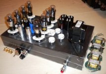
In the meantime, I finished my build. here a link to my thread.Ron's Aikido pictures
Talk about thread drift! 🙄
Ron
Where you been? Have not seen your pictures in a while. This used to be your thread.....LOL , we sorta hi-jacked it lately.
Sorry.In the meantime, I finished my build. here a link to my thread.Ron's Aikido pictures
Talk about thread drift! 🙄
Ron
Hi Ron!
No you didn't hi-jack my thread, you just borrowed it 😉 I don't mind at all!
And it wasn't off topic, it was just Aikido-stuff 🙂
Now it's a good thread with lots of information for aikido-builders! 🙂
Nice build! It looks cool! I must say your design is very unique!
And those round corners look good! Most commercial amplifiers I have see is often very edgy...
I have been building some other amps while I haven't been here...
Needed some more channels for my so called home theater 😉 Some day I will save up for a projector and then it will be a real home theater 😀
I have built a Gainclone chipamp. I think it sounds great! Really good value for the money!
Here it is:
It's actually one of my few finished projects 🙄 🙂
I think I will try my Aikido with it, but first I will make sure it's safe to do so!
Brit quoted this on page 2:
So I guess I will connect my scope and check first!
But my Aikido works well with my EL84 amplifier! I got it hum free, remember? 🙂
I think it's about 90% done. There are some adjustments left... Adjusting the B+, do some measuring, some more listening...
It's easier to start new projects than finishing old ones 🙂
I have also built ~75% of another chipamp with 3 LM3886 in parallel!
The heatsinks might be a little oversized 😉
I am also working on a OP-based preamp:
This is the chassis:
And this is a small mono SE-amp, half done:
I had all the parts at home except some resistors, so I couldn't resist to build a small amp of it 🙂
Maybe i will use it as a radio 🙂
Both transformers are taken from broken radios 😀
That's all for now! Next thing to do is finishing all projects! 😉
ps. Who is of topic now? 😀
No you didn't hi-jack my thread, you just borrowed it 😉 I don't mind at all!
And it wasn't off topic, it was just Aikido-stuff 🙂
Now it's a good thread with lots of information for aikido-builders! 🙂
Nice build! It looks cool! I must say your design is very unique!
And those round corners look good! Most commercial amplifiers I have see is often very edgy...
I have been building some other amps while I haven't been here...
Needed some more channels for my so called home theater 😉 Some day I will save up for a projector and then it will be a real home theater 😀
I have built a Gainclone chipamp. I think it sounds great! Really good value for the money!
Here it is:
An externally hosted image should be here but it was not working when we last tested it.
It's actually one of my few finished projects 🙄 🙂
I think I will try my Aikido with it, but first I will make sure it's safe to do so!
Brit quoted this on page 2:
Mixing a tube output and a solid state input can be hazardous to the health of the SS input!! The output cap will let a little bit of DC pass as it first powers up. It doesn't take much on the input chip of a SS amp to create conditions in which they can't survive.
quote:
"I have personally seen many blown amplifiers due to this and have also studied this in my development of directly driving tube stages into transistors in my hybrid amplifier designs."
So I guess I will connect my scope and check first!
But my Aikido works well with my EL84 amplifier! I got it hum free, remember? 🙂
I think it's about 90% done. There are some adjustments left... Adjusting the B+, do some measuring, some more listening...
It's easier to start new projects than finishing old ones 🙂
I have also built ~75% of another chipamp with 3 LM3886 in parallel!
An externally hosted image should be here but it was not working when we last tested it.
An externally hosted image should be here but it was not working when we last tested it.
The heatsinks might be a little oversized 😉
I am also working on a OP-based preamp:
This is the chassis:
An externally hosted image should be here but it was not working when we last tested it.
And this is a small mono SE-amp, half done:
An externally hosted image should be here but it was not working when we last tested it.
I had all the parts at home except some resistors, so I couldn't resist to build a small amp of it 🙂
Maybe i will use it as a radio 🙂
Both transformers are taken from broken radios 😀
That's all for now! Next thing to do is finishing all projects! 😉
ps. Who is of topic now? 😀
Back view of the preamp:
An externally hosted image should be here but it was not working when we last tested it.
Wow.. very nice work Olle. Good to see you back on the thread.
My work has been postponed for a little due to study, internal interviews at work etc.
Also got some parts stuck in customs here😡 😡
and been ripped off on ebay, goign through a paypal claim at the moment.
But I should get the soldering tip out again soon I hope. I miss those fumes!
I want to build some simple cathode followers and a SE amp.
Currently got my Aikido running through my SS Carver amp and Klipsch speakers and I'm amazed every time I turn it on. I love it so much. Never heard my albums sound so alive, so dynamic.
I've been collecting a load of new parts and valves.
I have some 6N6P tubes and I have swapped the 6N1P input tubes for the 6N6P's.
Initial impression is very nice indeed.
Not sure if I have Cathode resistor R2 set correctly.
I have 320 ohms for R2 and 300 for R11.
I'm reading 2.5V at R2 and 2.7V at R11.
So I figure the current through the input tube 6N6P is 2.5/320
= 7.8 mA.
Is this looking a little low??
Howdy Brit
Looked through several Aikido guides but can't find a 6n6p tube...
What's your B+? Just use the table if it's listed, find the tube, then the B+ you are using then read off the Rk.
Alternatively if you're running 1/2-2/3 of the max rated current you are probably in a comfortable operating point. There are no exact answers to best operating point so just try a few and if you feel you hear an improvement stick with it brutha!😀
The maths is correct as far as I can see.
Thanks Kendrick.
You're right. JB hasn't listed the 6N6P on his tables but I read somewhere (can't recall now) that the operating points were similar to the 6N1P.
B+ is 228.
Maybe someone somewhere is using the same.
Sounds great at first try. Better than the 6N1P's I had.
You're right. JB hasn't listed the 6N6P on his tables but I read somewhere (can't recall now) that the operating points were similar to the 6N1P.
B+ is 228.
Maybe someone somewhere is using the same.
Sounds great at first try. Better than the 6N1P's I had.
ollebolle said:
[IMGDEAD]http://vidingsjoserver.dnsalias.net/upload/lm3886trinity/monterat.jpg[/IMGDEAD]
[IMGDEAD]http://vidingsjoserver.dnsalias.net/upload/lm3886trinity/medkondingar.jpg[/IMGDEAD]
The heatsinks might be a little oversized ;)
[/B][/QUOTE]
Hi Olle,
Congrats to your projects!
BTW, I like alu "skeleton" hausing too.
I´ve heard somewhere: "There´s no too big heatsink in audio!" ;)
Cheers!
Need a little Aikido help
I'm getting my bill of material together for an Aikido build and there is something I don't understand. I'm probably missing the point and I hope someone will take the time to offer an explaination.
I have the 9-pin Aikido Schematic (Rev.A) and the attached table in front of me. In Broskie's first article, the cathode resistors (within a totem) were of the same value and that seemed to be the keystone of the design so that both triodes were loaded equally. On the drawing this would be R2 and R4 or R8 and R11 depending on the totem. This has not changed - correct?
The table shows values for "Rk" and I assume that these are the values for the Cathode Resistors. The previous column is headed "Rp" (Plate Resistor????) Which resistor would that be?
The values for R3, R9 and R-10 are listed as a range from 100 to 470. What factors should I consider when picking a value?
BTW, I'm using 6CG7s and 6DJ8s for the input and output stages respectively.
Thanks for the help.
Olle,
Very nice looking build of your amp(s). Good job! Beautiful workmanship
Those heat sinks on the chip-amp are HUGE!!! I could use those for my future Pass F5 build.
Thanks for the pictures.
Ron
Very nice looking build of your amp(s). Good job! Beautiful workmanship
Those heat sinks on the chip-amp are HUGE!!! I could use those for my future Pass F5 build.
Thanks for the pictures.
Ron
I'm also working on Aikido...
An externally hosted image should be here but it was not working when we last tested it.
Re: Need a little Aikido help
Captn D
R2=R4 and R8=R11 yes. Nothing changed here. Rk is the cathode resistor as you mentioned. Rp if I'm not mistaken is the resistor in series with the plate, usually around 300R which is the R3,9,10 you speak of.
I noticed you haven't mentioned the plate voltage you are using. This will dictate the values you need in Rk positions. You need to read off the table at the back first for tube type in each stage and then B+. For example 6CG7 you can see can operate from 150 to 350V B+ and the Rks range from 583 to 352R respectively. Note however that at 150V you are running 3mA whereas at 350V you'd be running 10mA. There is no single right answer here. However...
Because your secondary stage is 6DJ8 the range of B+ is similarly wide but skewed lower from 100V-300V.
Let's say your B+ is 200V. Rk for R2 and R4 is 397R. For the 6DJ8 R8 and R11 should be 205R. I wouldn't sweat too much on the exact values, as long as they are the same.
Assuming you are running as a preamplifier (not headphone) you will need R15 to be 87.5k (read off the output tube R15 value at B+ of 200V). This could also be implemented using a fixed resistor and a pot (0.5W or greater) to help null noise. Don't forget to omit C8 (sometimes mislabeled on some versions of the PCB as C6 from recollection). Trace the circuits with a multimeter if you are unsure.
If you read the article again in full and follow his examples I think you'll soon work out how to use the table.
Hope that helps. Cheers.
Captn Dave said:
SNIP
I have the 9-pin Aikido Schematic (Rev.A) and the attached table in front of me. In Broskie's first article, the cathode resistors (within a totem) were of the same value and that seemed to be the keystone of the design so that both triodes were loaded equally. On the drawing this would be R2 and R4 or R8 and R11 depending on the totem. This has not changed - correct?
The table shows values for "Rk" and I assume that these are the values for the Cathode Resistors. The previous column is headed "Rp" (Plate Resistor????) Which resistor would that be?
The values for R3, R9 and R-10 are listed as a range from 100 to 470. What factors should I consider when picking a value?
BTW, I'm using 6CG7s and 6DJ8s for the input and output stages respectively.
Thanks for the help.
Captn D
R2=R4 and R8=R11 yes. Nothing changed here. Rk is the cathode resistor as you mentioned. Rp if I'm not mistaken is the resistor in series with the plate, usually around 300R which is the R3,9,10 you speak of.
I noticed you haven't mentioned the plate voltage you are using. This will dictate the values you need in Rk positions. You need to read off the table at the back first for tube type in each stage and then B+. For example 6CG7 you can see can operate from 150 to 350V B+ and the Rks range from 583 to 352R respectively. Note however that at 150V you are running 3mA whereas at 350V you'd be running 10mA. There is no single right answer here. However...
Because your secondary stage is 6DJ8 the range of B+ is similarly wide but skewed lower from 100V-300V.
Let's say your B+ is 200V. Rk for R2 and R4 is 397R. For the 6DJ8 R8 and R11 should be 205R. I wouldn't sweat too much on the exact values, as long as they are the same.
Assuming you are running as a preamplifier (not headphone) you will need R15 to be 87.5k (read off the output tube R15 value at B+ of 200V). This could also be implemented using a fixed resistor and a pot (0.5W or greater) to help null noise. Don't forget to omit C8 (sometimes mislabeled on some versions of the PCB as C6 from recollection). Trace the circuits with a multimeter if you are unsure.
If you read the article again in full and follow his examples I think you'll soon work out how to use the table.
Hope that helps. Cheers.
Re: Re: Need a little Aikido help
I am using the chassis from an old integrated amp which comes to me with a 275vct transformer and a 6CA4 rectifier. I'm planning a CRC with 150 & 220 uf caps and a 750R step resistor. I did this with the assistance of PSUII. The product at 40ma should be 300vdc.
At 300vdc im using +/-243 and 845 ohm resistors for the 6CG7 and 6DJ8 respectively. This will give me a 10ma 6CG7 and a 5ma 6DJ8 at 300vdc. (Come to think of it I need to change the value of my step resistor to yield 300vdc at 30 ma!) R15 is 86.8K since I'm using the higher voltage.
I was curious about the headphone comment. I had considered making the design flexable enough to accomodate headphone use. Do I use a different value of R15 for phones? Where can I read about that? It's something I had missed.
Again, thanks for the comments and any explanations on the Rp value would be appreciated. I'll post some photos when I get some solder flowing.
CD
Thanks for your comments, they are very helpful. I still have a problem with the Rp values though. First, the R3,9,10 resistors look to me to be in series with the grid rather than the plate. Their listed values are an order of magnitude higher than we would expect; for instance 7.5K for the 6CG7 at 300 vdc. Oddly, I have values for every resistor in the circuit (Rp is like the gear left over once the case is bolted up) The only plate resistors I see are the R4,8 resistors which are really cathode resistors. I'm stumped.Silver Stealth said:
R2=R4 and R8=R11 yes. Nothing changed here. Rk is the cathode resistor as you mentioned. Rp if I'm not mistaken is the resistor in series with the plate, usually around 300R which is the R3,9,10 you speak of.
I noticed you haven't mentioned the plate voltage you are using. This will dictate the values you need in Rk positions. You need to read off the table at the back first for tube type in each stage and then B+. For example 6CG7 you can see can operate from 150 to 350V B+ and the Rks range from 583 to 352R respectively. Note however that at 150V you are running 3mA whereas at 350V you'd be running 10mA. There is no single right answer here. However...
I am using the chassis from an old integrated amp which comes to me with a 275vct transformer and a 6CA4 rectifier. I'm planning a CRC with 150 & 220 uf caps and a 750R step resistor. I did this with the assistance of PSUII. The product at 40ma should be 300vdc.
Assuming you are running as a preamplifier (not headphone) you will need R15 to be 87.5k (read off the output tube R15 value at B+ of 200V). This could also be implemented using a fixed resistor and a pot (0.5W or greater) to help null noise. Don't forget to omit C8 (sometimes mislabeled on some versions of the PCB as C6 from recollection). Trace the circuits with a multimeter if you are unsure.
At 300vdc im using +/-243 and 845 ohm resistors for the 6CG7 and 6DJ8 respectively. This will give me a 10ma 6CG7 and a 5ma 6DJ8 at 300vdc. (Come to think of it I need to change the value of my step resistor to yield 300vdc at 30 ma!) R15 is 86.8K since I'm using the higher voltage.
I was curious about the headphone comment. I had considered making the design flexable enough to accomodate headphone use. Do I use a different value of R15 for phones? Where can I read about that? It's something I had missed.
Again, thanks for the comments and any explanations on the Rp value would be appreciated. I'll post some photos when I get some solder flowing.
CD
Re: Need a little Aikido help
Mystery Solved.
I post this only to assist others who may have the same misunderstanding. The column labeled Rp refers to the tubes dynamic plate resistance, "rp", not a resistance value.
Of course, Dynamic Plate Resistance is an operating characteristic of the tube (as are gm and mu).
CD
Captn Dave said:
The table shows values for "Rk" and I assume that these are the values for the Cathode Resistors. The previous column is headed "Rp" (Plate Resistor????) Which resistor would that be?
Mystery Solved.
I post this only to assist others who may have the same misunderstanding. The column labeled Rp refers to the tubes dynamic plate resistance, "rp", not a resistance value.
Of course, Dynamic Plate Resistance is an operating characteristic of the tube (as are gm and mu).
CD
That's right, Captn I should have clued on likewise earlier. There are no plate resistors in this design, the B+ is split equally between the tube halves via the 1M resistors.
As far as the headphone operation there are 3 main changes I can see:
1) Use R17 - value again picked from the table depending on B+ and output tube selected (100R-600R approx)
2) Short R15 and R8
3) Insert C8 over R11 (47uf-1k uf 10V)
As far as the headphone operation there are 3 main changes I can see:
1) Use R17 - value again picked from the table depending on B+ and output tube selected (100R-600R approx)
2) Short R15 and R8
3) Insert C8 over R11 (47uf-1k uf 10V)
- Home
- Amplifiers
- Tubes / Valves
- Building a Aikido preamplifier