boywonder said:
PSUDII shows a nice smooth voltage rise with no overshoot. I have access to a scope but so far, I am a complete knucklehead when it comes to operating it. This will be another great exercise for my scope education.
LOL,
that's why I don't own a scope yet! Glad to see someone else is as honest as I am about admitting what they don't know.

I have simulated (sort of) my PSU with PSUDII with an 8H choke and it works out to be the bare minimum for my voltage and load requirements. I substituted a 30H and it looks good too, I must have done something wrong the other day.....Hmmmm. I would have prefered a 15H but I had the 8 on hand.
Ron
If you are thinking about measureing the B+ with a scope, make sure the scope can handle the voltage!
My multimeter can handle 700VAC and 1000VDC.
My scope is far from that!
But there might be better scopes than mine! 🙂
If I want to look at B+ with my scope I use to add 20M in series with the probe.
The scale at the screen will be incorrect, but my scope survives 🙂
A better way to do it is to build some kind of attenuation! It would be great to choose between 10:1 or 100:1...
Maybe next project for me 🙂
Damn!! this worked fine at work but not on my laptop at home.
Very strange. It doesn't give me the option of opening it.
Doesn't work with Excel does it? (as I don't have this at home).
If the scopes input impedance/resistance is constant I think a voltage divider will do!
That is not a big project 🙂
That is not a big project 🙂
ollebolle said:If the scopes input impedance/resistance is constant I think a voltage divider will do!
That is not a big project 🙂
Olle,
I agree about a voltage divider circuit, I remember reading about this somewhere on this forum.....God only knows where. It would be easy to make a multifunction switch box with various ratios. I should start saving for a good scope, about how much $$$ are we talking about? How much should I expect to pay for a decent scope?
Ron
Brit01 said:
Damn!! this worked fine at work but not on my laptop at home.
Very strange. It doesn't give me the option of opening it.
Doesn't work with Excel does it? (as I don't have this at home).
PSUDII doesn't need excel as far as I know, just runs on it's own.
I am using a PSUDII model for Bas' PSU board from post #409 in this thread (Thanks Sheldon)
http://www.diyaudio.com/forums/showthread.php?s=&threadid=60585
It seems to be the most accurate representation of the split output R's and C's. In other words, the values in the PSUD model for C3 and R1 are doubled for the output 47 uf C's and halfed for the output R's. The constant current load is the combined load of both channels, I'm using 40ma for the load. Once you get PSUD up and running, attempt to duplicate the model in post #409 from the thread above.
It seems to be the most accurate representation of the split output R's and C's. In other words, the values in the PSUD model for C3 and R1 are doubled for the output 47 uf C's and halfed for the output R's. The constant current load is the combined load of both channels, I'm using 40ma for the load. Once you get PSUD up and running, attempt to duplicate the model in post #409 from the thread above.
The load would be the sum of the cathode currents?
 Not sure about this.
Also I'm reading 51 ohms across the secondary windings of the 275V tranny.
Brit01 said:
The load would be the sum of the cathode currents?
Also I'm reading 51 ohms across the secondary windings of the 275V tranny.
Start by assuming that the total current draw from the PS is 40 ma. You can tweak the model to look like real life by changing load current, etc. Yes it would be the sum of the cathode currents.
Perfect, use 51 ohms in PSUD for the tranny R.
You want the output voltage V(I1) to have minimal ripple, and little or no ringing/overshoot. Once you get the circuit modeled, click the V(I1) box and simulate.
You will need to zoom in on the voltage trace to check the ripple voltage.
After all that, you can also check for ringing/overshoot with a stepped load. You input stepped load in the constant current input box. Step it from 40 ma to 50 ma after 5 seconds or so to see if you get any ringing of the voltage with changing current. You want the timing of the load step to be during the steady-state portion of the voltage, so make sure the voltage is done rising (or settling) before applying the step (that's why I picked 5 seconds, YMMV)
Thanks a lot boywonder.
Does anyone fancy trying this for me as I just can't get the psud to download at home??.

And tell me what would be the best values for the caps and resistors?
Does anyone fancy trying this for me as I just can't get the psud to download at home??.
And tell me what would be the best values for the caps and resistors?
yipeee
don't worry. I got it working.
I downloaded it from my pendrive at work and added it through the control panel.
don't worry. I got it working.
I downloaded it from my pendrive at work and added it through the control panel.
Brit01:
Learn how to use it; it's totally worth it, and it's quite intuitive once you figure it out.
Learn how to use it; it's totally worth it, and it's quite intuitive once you figure it out.
You will need to zoom in on the voltage trace to check the ripple voltage.
What would be a good amount of ripple?
If I use
C1: 470nF
C2: 100uF
C3: 200uF
R1: 1K
R2: 500
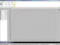
I get just a diff of 72 mV. This is the ripple right? The diff between the min and max Voltage.
Seems to reach 227 V after about 6/7 seconds.
This is cool stuff!
If I adjust the reporting delay to 10 secs and add 4.2 uF as C1 I only get 7 mV ripple. Almost flat.
After all that, you can also check for ringing/overshoot with a stepped load. You input stepped load in the constant current input box. Step it from 40 ma to 50 ma after 5 seconds or so to see if you get any ringing of the voltage with changing current. You want the timing of the load step to be during the steady-state portion of the voltage, so make sure the voltage is done rising (or settling) before applying the step (that's why I picked 5 seconds, YMMV)
This is all new stuff for me.
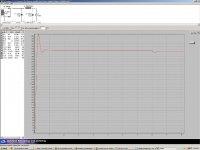
I plugged in this date as you mentioned. What am I looking at? How do interpret the downward falling curve?
Seems to drop 1.47 Volts after about 2 and a bit seconds.
Brit01 said:
This is all new stuff for me.
I plugged in this date as you mentioned. What am I looking at? How do interpret the downward falling curve?
Seems to drop 1.47 Volts after about 2 and a bit seconds.
Are the actual final caps on your PS board 100uf each and the final resistors are 1kohm? What is the secondary voltage of your transformer?
With your values above, assuming that your transformer secondary is 250V, I got this, which looks good:
If I try your 4.2 uf C1 value in the model shown, PSUD is giving me an error message that I'm exceeding the forward current of the 6X5.....
Attachments
secondary is 275V
Current caps are 0.47/100/100
and resistors 1K/1K
We are interested in the ripple after the Voltage has settled to max right?
Current caps are 0.47/100/100
and resistors 1K/1K
We are interested in the ripple after the Voltage has settled to max right?
Brit01 said:secondary is 275V
Current caps are 0.47/100/100
and resistors 1K/1K
Brit01: I just edited my post above. Are you seeing an error mesage when you simulate? Using 4.2u C1 with 250 volt secondary PSUD says that you are exceeding the forward voltage of the rectifier, and using .47u with 275V secondary I also get the message. You may be on the ragged edge of arcing over the 6X5. It appears to be just over the limit for the 6X5 data in PSUD.
Yes, your ripple looks good, about 20mv in my sim.
Yes I got that.
But not with 0.47/100/200
and resistors 1K/500
load 40mA
rectifier 6X5GT
275V (51 ohms)
But not with 0.47/100/200
and resistors 1K/500
load 40mA
rectifier 6X5GT
275V (51 ohms)
Brit01 said:Yes I got that. So I reduced this to 0.47uF and it's much happier.
It appears that you can reduce C1 (and C2) further with little impact on B+ or ripple to give yourself additional safety margin on the 6X5. Changing C1 impacts the excessive forward current more than changing C2.
- Home
- Amplifiers
- Tubes / Valves
- Building a Aikido preamplifier