It is not resistance but characteristic impedance:
http://www.speedingedge.com/PDF-Files/BTS002_Characteristic_Impedance.pdf
Fig 3 shows why for high frequency signals (all digital) why the return path should close to the signal.
Characteristic impedance - Wikipedia, the free encyclopedia
http://www.speedingedge.com/PDF-Files/BTS002_Characteristic_Impedance.pdf
Fig 3 shows why for high frequency signals (all digital) why the return path should close to the signal.
Characteristic impedance - Wikipedia, the free encyclopedia
QUOTE / I can take a SPDIF Out from my PC with 75 Ohms cable and terminate BNC connector (Male) at another end.
only good if the pcb card have a BNC output or you need to solder on the card the cable if no BNC output instead of the RCA (if you have a rca spidf output on the card : keep the rca but solder the cable on the holes - take care to the card and EMS...
Conectors should be like this for something standard : cable : jack to jack ; devices : plugs ; exactly like RCAs do on commercial devices but this time with true 75 ohms & BNC connectors for the digital.
Always insulate RCA on all devices from the cases to avoid massive gnd loop. Go to Marce advice if you can about the small shunt smd with gnd but if you can't : go for insulation with all the analog RCAs with the cases.
Only power plug GND pin has to be connect to the case for security. Avoid the gnd of the audio circuits to be connect to the case (or massive ground loop) : let the pcbs analog gnd floating with PS (not connected) : the devices are conected together via the Gnd analog wire for the return path ! Not by their cases 😱 !
Friends are to have good time and drink a beer, not to follow them for all the fools things they do...
Gents, unusual question.
I have assembled dac + psu, tested once- no joy, silence.
As I remember, all measurements were fine, but possibly I missed something while assembling months ago.
Problem is- I have no time now for troubleshooting dac, starting my first business and it takes all my time away.
Would anybody help to check soldering and see if any resoldering needed, etc.
I can send it by post, ideally UK.
I would return the favour.
PM me please 🙂
Otherwise I ll have to wait until end of july to do my checks...
Voxonline,
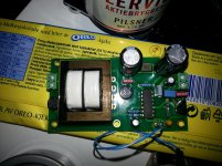
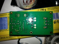
Try before to take two pictures from the two pcbs at 90° (above the pcbs) maybe we can help you before increase the global warming with sending your dac everywhere?!
So you have checked all the values than Korben writed on a photograph before in this thread... All ? PS PCB ? 5V output ? The four LDO regs, output pin ok with the values ? No short between the leads or copper fil somewhere, check also the spidf pins...
I had something near your symptom, but when I re checked the values I saw some of them was mooving like with a cap near the Wolfson pins : I had a cold joint like GaryB said to me just before : Flux+ magnyfing glass let able me to resolder the joint just putting the solder iron on the beginning of the active devices leads (2 chips and four ldo regs). Crystal voltage are good ? top of the case buzz when a gnd pad in serie with the buzzer ? 1.6 V at the output of the crystal ?
Good evening !
Miss this forum badly, just not enough time for diy 🙂
I suspect it could be cold joint,as I was doing soldering veeeeery gently.
I ll do my measurements then and get back- I hope I can rectify this problem.
Miss this forum badly, just not enough time for diy 🙂
I suspect it could be cold joint,as I was doing soldering veeeeery gently.
I ll do my measurements then and get back- I hope I can rectify this problem.
if no time just read the first page of this thread,
there is this link on it also: http://www.diyaudio.com/forums/digi...-building-subbu-dac-v3-se-92.html#post3869957 : the voltage values....
and the errors to avoid like an inverted polarity on one of the tantalum caps (error of printing on the pcb, maybe just that for you) :
there is this link on it also: http://www.diyaudio.com/forums/digi...-building-subbu-dac-v3-se-92.html#post3869957 : the voltage values....
and the errors to avoid like an inverted polarity on one of the tantalum caps (error of printing on the pcb, maybe just that for you) :
Just to let you guys know... my recently aquired Subbu DAC with the short to the groundplane is repopulated with parts and playing music beautifully.
I replaced two of the Micrel regs and all the capacitors before the regulators... not all were bad probably but I didn't want to take a chance.
For the electrolytics I used Panasonic SEPC this time, so after this DAC has got some mileage I might report on the other thread whether there are noteworthy differences to my other one. 😉
Just to let you guys know... my recently aquired Subbu DAC with the short to the groundplane is repopulated with parts and playing music beautifully.
I replaced two of the Micrel regs and all the capacitors before the regulators... not all were bad probably but I didn't want to take a chance.
For the electrolytics I used Panasonic SEPC this time, so after this DAC has got some mileage I might report on the other thread whether there are noteworthy differences to my other one. 😉
I hope you keep the C18 with the UCC polymer ASA serie if you used SEPC at C22. Give better subjective result for me instead SEPC both populated.
My tests was without the JG buffer also !
Last edited:
Hi all!
Recieved all my parts for the DAC today, so I'm ready to start assembly. 🙂 The things I'm missing though, are the BOM and schematic, could any of you be so kind as to send them to me, or point me in the direction of a download-link? brillebjorn@gmail.com
Regards
- Bjørn
Recieved all my parts for the DAC today, so I'm ready to start assembly. 🙂 The things I'm missing though, are the BOM and schematic, could any of you be so kind as to send them to me, or point me in the direction of a download-link? brillebjorn@gmail.com
Regards
- Bjørn
Question guys: I seem to be missing the CLED-cap for the PSU, don`t know if it was missing when I got the parts, or if I lost it somewhere. 😕 I do have som leaded 10uF 25V Tantalum-caps laying around, any ill-effects from putting one of those in CLED-position? And how about polarity, the + still goes to the positive side of the LED, yes?
Regards
- Bjørn
Regards
- Bjørn
use the buzzer on the pcb to see which polarity goes to gnd with the soldering pads in relation to the caps.
If a golded pad buzz with the gnd : you put the tantalum with the side without marking (the mark on the tantal cap is for + : so for the pads which buzz with the led vias which not buzz to gnd). But on my PS the + of the cap is near the led where its marked "+"
If a golded pad buzz with the gnd : you put the tantalum with the side without marking (the mark on the tantal cap is for + : so for the pads which buzz with the led vias which not buzz to gnd). But on my PS the + of the cap is near the led where its marked "+"
Question guys: I seem to be missing the CLED-cap for the PSU, don`t know if it was missing when I got the parts, or if I lost it somewhere. 😕 I do have som leaded 10uF 25V Tantalum-caps laying around, any ill-effects from putting one of those in CLED-position? And how about polarity, the + still goes to the positive side of the LED, yes?
Regards
- Bjørn
Please use the 10 uF ceramic cap. This cap originally was intended as an easter egg. Our new project also has the 10 uF cap over the LED... as it turned out to make a small difference in reality.
There is no hurry, the PSU will work fine without it. You can order the 10 uF when you start a new project and solder it then.
Last edited:
Thanks for your input guys!
I was brave(and stupid??) and soldered on the tant-cap, and it worked like a charm! PSU-outputs 4.973VDC at X2, and the led dims slowly when power is disconnected. 😀
I will however order and change it next time I put in an order at Mouser. 😉
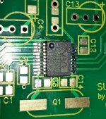
Now on we go with the DAC-board! Just soldered the WM8804, by drag-soldering, worked sweet!
Regards
- Bjørn
I was brave(and stupid??) and soldered on the tant-cap, and it worked like a charm! PSU-outputs 4.973VDC at X2, and the led dims slowly when power is disconnected. 😀
I will however order and change it next time I put in an order at Mouser. 😉
Now on we go with the DAC-board! Just soldered the WM8804, by drag-soldering, worked sweet!
Regards
- Bjørn
Attachments
Won't it be difficult to work on the PSU when the LED cable is soldered instead of using the small Molex KK connector ?
BTW some joints need some more solder, like one of the secondary pins of the transformer...
BTW some joints need some more solder, like one of the secondary pins of the transformer...
Only work I'm doing on the PSU, is changing the CLED, and I'll manage to do that with the cable attached. The cable and led are measured to length to go where I want it on the chassis-front. ;-) I got all my parts through Phil, and he did not provide the molex-connector for this led, so I figured I'd just make it permanent the first time, so I wont have to solder it again.
Thanks!
Regards
- Bjørn
Thanks!
Regards
- Bjørn
Yeah, I have a fear that my claim about not doing any more work on it, might bite me in the *** one day. ;-)
Of course, I screwed up on the mic-regs, soldered U4 in U1-position.. Luckily I found my second soldering-iron, so removing it was a breeze. 🙂
Of course, I screwed up on the mic-regs, soldered U4 in U1-position.. Luckily I found my second soldering-iron, so removing it was a breeze. 🙂
- Home
- Source & Line
- Digital Line Level
- Build thread - building the Subbu DAC V3 SE