Héhé,
Dictionnaries are not very fast on Internet ! I will buy an harraps CD dictionnary !
For a long time I believed the name of a DAC in english was WM (washing Machine)... But strangly when I travel in India they understand me more than an english guy.... c'est bizarre !
So It's time for dinner, bratwurst & glass of red wine...
I give up the soldier....shxxxt... the solder.
Last edited:
Mois je ne mange pas le Bratwurst mais j'aime beaucoup un verre de vin rouge... parfois le St. Emilion 😉
Pardon les mods pour cette excursion...
Pardon les mods pour cette excursion...
Better is the Pomerol... (but not the Lalande-Pomerol) if you can find it...the plot of land of Pomerol is much more little than the St Emilion one. Very near in distance (few kilometers)... but not at all the same taste...
the magic of wine... not only the sun for sure !
ouais pardon les mods !
the magic of wine... not only the sun for sure !
ouais pardon les mods !
.Yes you must have a short in DAC No1 when the LED switches off... so like I said before inspect for solder bridges and/or bad joints. What kind of solder are you using since it really piles up in places on your board?
I cannot see any visible bridges. I will remove each reg one by one in order to identify the culprit. Presently all regs are buzzing. I strongly suspect U4 as this reg was put the last. Prior to this U3, U5 and U6 had no buzz and were ok. So U4 will be my first target.
Will do it over the weekend when I get enough time to work on it as I will need to remove parts surrounding the U regs to get enough space to work. Weekdays are usually busy for me.
I am using good quality 0.5mm 60/40 solder wire and thin tip. Since space between 'U' regs legs is less I carry a little solder on the tip and solder. The tip being thin is unable to carry enough solder at one go so I end up piling solder on the legs little by little.
I will try to change to a flat thin tip if required which will carry enough solder at one go.
I use these tips right now.
An externally hosted image should be here but it was not working when we last tested it.
You have maybe to consider a broken reg maybe with a shortcut (because PS was switched on before testing all manually).
The reg doesn't seem to be broken but I will only find out once I remove them. Hopefully the regs are a problem especially U4 which can be sorted out.
I intend to complete the build and have the DAC up and running. Hopefully the weekend will give me sufficient time to check out the suspected parts. I will keep everyone posted.
Stixx and Eldam, thanks once again for your inputs.
I'm sure you will find the problems step by step.
WOW they are so little. But maybe they are worn, not able to carry few solder but just an heavy drop of solder (your pcb pictures...), maybe your skill, I don't know...
WOW they are so little. But maybe they are worn, not able to carry few solder but just an heavy drop of solder (your pcb pictures...), maybe your skill, I don't know...
Dmm shows zero volts at x1 of dac when connected to the Psu and led of psu switches off
When I disconnect the psu thd led switches on. Also with the psu disconnected sgen I run the buzzer on x1 of dac it buzzes.
When I check the output of the psu without connecting to the dac it shows 5v.
For some reason the power gets cut off when I connect to the dac.
Sent from my GT-N7100 using Tapatalk 2
As said earlier ,I get continuity beween ground and SPDF +ve input (terminal block).When I remove R2,it disappears.So what can it be?Purposely R2 is not placed correctly for testing.Please have a look and guide me.
Sorry for bad photos,taken from mobile camera.
An externally hosted image should be here but it was not working when we last tested it.
An externally hosted image should be here but it was not working when we last tested it.
An externally hosted image should be here but it was not working when we last tested it.
Sorry for bad photos,taken from mobile camera.
I also ran a buzzer test on the tantalums like Eldam recommended. C5 C7 C19 and C20 are buzzing and so is L2.
When U use the buzzer on the U3, 4, 5 and 6 regs on legs (pins) 1 and 2 or 2 and 3 it buzzes. This shouldn't happen.
There seems to be a short somewhere.
When U use the buzzer on the U3, 4, 5 and 6 regs on legs (pins) 1 and 2 or 2 and 3 it buzzes. This shouldn't happen.
There seems to be a short somewhere.
Last edited:
So, you say that dac psu shown 5v when no dac connected and when connect dac is like a short circuit.
Simulate the dac consumption with a 50r 1-3w resistor and see if the behaviour remains. Maybe your power transistor from psu is installed backwards.
With your dmm you should read 75r on ohm-meter on spdif signal input, not short.
Simulate the dac consumption with a 50r 1-3w resistor and see if the behaviour remains. Maybe your power transistor from psu is installed backwards.
With your dmm you should read 75r on ohm-meter on spdif signal input, not short.
Last edited:
So, you say that dac psu shown 5v when no dac connected and when connect dac is like a short circuit.
QUOTE]
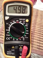
Yes you got this right, Its between 4.98v - 5V when no Dac is connected.
With reference to 75r on spdif input signal X2/R2 shows 75.9r on dmm on ohm meter (of course without PSU connected)
Some pics of the PSU for your reference. Power Supply is 230v-240v.
An externally hosted image should be here but it was not working when we last tested it.
An externally hosted image should be here but it was not working when we last tested it.
An externally hosted image should be here but it was not working when we last tested it.
Attachments
Try to simulate dac by a dummy resistor and see if the psu is behaving the same.
Also you can power dac from battery 6volt will do it, maybe your psu is the problem.
You have a good opportunity to learn a bit of circuit troubleshooting by isolating the issue on some module.
Also you can power dac from battery 6volt will do it, maybe your psu is the problem.
You have a good opportunity to learn a bit of circuit troubleshooting by isolating the issue on some module.
How do I simulate DAC by a dummy resistor?
PSU could be a problem. I did have a problem on X1 of PSU which got shorted by mistake due to loose wiring and burnt a terminal block at PSU X1. Nothing else was burnt. I changed the terminal block at X1 and wired properly. As the output was showing 5v so I didn't bother more about the PSU.
Maybe I will try a different PSU and check over the weekend.
Also why does the X1 of the DAC buzz without the PSU connected. There has to be a short in the DAC somewhere?
Hi I think your building of the DAC has become a failure. Sorry but looking at the pics I can only advise to learn soldering somewhat better before undertaking SMD projects. It looks many parts are overheated.
Sorry.
Sorry.
JP I appreciate your honest opinion. This was my first SMD project.
Sent from my GT-N7100 using Tapatalk 2
Sent from my GT-N7100 using Tapatalk 2
You have learnt quite some things in the process so don't feel bad about it. A second project will be better (that does not necessarily have to be a V3 DAC). If you want to take a second chance please get in contact with Subbu as there are some boards left. Just think of the results when you have one playing. You could use this one as a project to learn soldering and desoldering. Just try to solder parts off the board for a change. Then clean the board and resolder all parts again. You will notice a feeling that you are the master and the board needs to listen to you 😉
It looks like you used lead-free solder ?! I want to advise on using good quality 60/40 tin-lead solder. Preferably 0.7 mm or thinner. In fact you will have better looking and better functioning joints with 60/40 solder and parts need not to be heated as much.
BTW you should use a smaller SEPC 470 µF for C22. There is only 3.6 V there so you can use a lower voltage rated version than the one you used now.
Last edited:
@spirovious - I don't consider myself an expert, but I did practiced using a $.70 copper pipe cap from the local hardware store and some junk SMD parts. Really like the Chip-Quick paste flux in the syringe even if the solder has flux.
I also made the mistake of using "fat" solder when I started the V3. You can see that on some posts on the GB thread. JP's advice to use the thin stuff made a world of difference.
I also made the mistake of using "fat" solder when I started the V3. You can see that on some posts on the GB thread. JP's advice to use the thin stuff made a world of difference.
You have learnt quite some things in the process so don't feel bad about it.
Thanks JP. I do not feel bad. Its been a positive learning experience for me. Prior to this I have done some thru hole soldering so SMD was totally new to me. Even after all the trouble and frustration I have enjoyed the build even though it has been a failure of sorts. Other DIY'ers builds are motivating enough for me to give it another try.
I have got in touch with Subbu and he has arranged for a PCB for me. I am very keen to complete this project and wouldn't dream of leaving in half way. I did plan to use the old board as practice 😀
I am using 60/40 solder of 0.5mm. I am having trouble with the solder iron tip. For U1, U2 and the other U regs should I carry a little solder on the tip or should I just solder the normal way of letting the solder flow from the wire to the iron. The reason I ask this is that the thin tip I use (see the pic I have posted earlier) is unable to carry enough solder on the tip and I end up adding more solder than required.
I tried to use a Nichicon in C22. Maybe I should change back to the Panasonic.
Any expert advice for me?My issue is SPDF signal is grounded and when I remove R2 from circuit,it is not.So what can I do?
- Home
- Source & Line
- Digital Line Level
- Build thread - building the Subbu DAC V3 SE