Sorry, please use the link in the first post of this thread - or this one - till I can work with the admins to correct the error.
Thanks for the heads up 😉
Thanks for the heads up 😉
BTW you know the info on C4, C22 and C32 ?
Ah, I thought for a moment you were talking about the c32/c35/c31 thing.
I've had a look at the modifying thread, and see where people have had good results with different C4 C22, C18, C32.
I've just used what came in the parts group buy. To be honest, I'm probably going to leave this project pretty much alone as it is now (Assuming I'm satisfied after some critical listening) I don't want to mess with it and screw it up. I bought two kits though, so on the next one I'll be more confident to experiment. Thanks for the heads up anyway 🙂
At some stage I'll take it down to my friend who works at a fancy hifi store, and we can compare it to his multi thousand $ DAC's. Just for fun 😀
Cheers,
Mark
Haha!
At this level I feel that "better" is a matter of tiny degrees of really good already and somewhat opinion.
I'll be happy if it's somewhere in the ballpark. 😀
Then I'll watch his face when I tell him how much I spent on it hehe. 😎
Cheers,
Mark
At this level I feel that "better" is a matter of tiny degrees of really good already and somewhat opinion.
I'll be happy if it's somewhere in the ballpark. 😀
Then I'll watch his face when I tell him how much I spent on it hehe. 😎
Cheers,
Mark
Guys I am facing a problem with 2 dac builds.
DAC 1:
- PSU working properly and outputting 5v.
- When I connected the PS to the DAC board to check voltages at L2, L3, L4 and L5 I found that the power was not entering the DAC. On doing a continuity test on X1 the buzzer rang.
What could be the problem?
Below are some pics of this DAC. C22 is soldered temporarily. Once L4 checks out and is soldered C22 will be soldered flush to the PCB.
DAC 2:
- L5 voltage is showing 3.1v. L2, L3 and L4 shows correct voltage.
Attachments
Hello All
I completed my build but to my dissapointment it is not working.
My PSU is showing correct 5.0v
Before soldering L3, 4, 5, 6, i had checked and all the values were correct.
All parts were used given by Korben except C17 and C22.
Attached is the picture of my build. Can someone suggest how can i proceed further.
For testing purpose i have used cat5 cables for spdif in and analog out.
Thanks
Attachments
Some of your solder joints are looking a bit dubious (cold) and you have used way too much solder on some of them.
I would check the voltages around the two IC's... someone has posted nice tables with the voltages earlier in the thread.
I suspect that you have power at the regs but something down the way is messed up.
Also C22 is damn close to some solder pads nearby and could be making unwanted contact...
I would check the voltages around the two IC's... someone has posted nice tables with the voltages earlier in the thread.
I suspect that you have power at the regs but something down the way is messed up.
Also C22 is damn close to some solder pads nearby and could be making unwanted contact...
Hello all,
I got the kit from one of my friend and built it according to the guide.But my problem is after taking all the correct readings,when I tried running it,there is no sound.I am not able to find out the fault.The only thing I found is my spdf input shows continuity.That is +ve and -ve and shows connected to each others in the circuit.I thing my spdf signal is getting grounded.I could hear the click sound when I turn on and off the DAC like any circuit make a sound.
So please help me to find out the possible problem.
Thanks.
CoolestOne,
connecting your first DAC to the psu you don't have any readings on the mentioned L-pads?? That is a very short way from the input X1 to L2... so I wonder what went wrong here?
Your images are way too small to do any troubleshooting, pls. post some higher res images. Other than that you can only proceed with the usual steps: visually inspect ALL solder joints with a magnifying glass, carefully reflow the ones that look iffy and try again. You should at least have readings at all inductors before you take the next steps.
PS. I don't have any experience with the used regulators so can't comment whether 3.1V is acceptable. Have you checked further down, like around the chips (see what I said to Darshanjoshi)?
Last edited:
Coolestone, Spirovious:
Maybe 3 photagraphs could help to help you : the first with the two PCB connected together; the others photographs a zoom on each pcb.
Maybe 3 photagraphs could help to help you : the first with the two PCB connected together; the others photographs a zoom on each pcb.
Coolest1,
DAC 1
Have you 5V on the 5V mentioned screw of X1 when GND voltmeter is put on the other screw ? Look at the PCB screen picture if the connector hide the "5V" mark on the PCB.
(problem with wires between the PSU and main board ? shortcuts on X1... argh ?)
DAC 2 : offical BOM for the LDO regs ? I have a similar problem with one pin of a reg which lake of soldering... check also if shortcuts on the regs pins with X10 glass and DC buzzer... but I think if similar to my problem there is one pin of the five wich lake soldering...
Last edited:
STIXX and Eldam,
DAC 1:
PSU is outputting 5v at X2. LED of PSU lights up. As soon as I connect PSU PCB (X2) to the DAC (X1) the LED of PSU switches off. X1 5V and Ground connected properly but current not flowing from PSU to DAC hence I am unable to check the L values as no current seems to be flowing into the DAC and X1 shows 0 volts when connected to PSU.
When I did a connectivity test on X1 without connecting to the PSU 5V I got a buzz. Maybe something short somewhere.
DAC 2 (my friends Dac):
I managed to get the correct reading on L5. One of the legs of U5 wasn't soldered sufficiently. Re-soldering it corrected the problem.
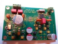
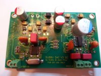
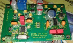
Some pics of DAC1
DAC 1:
PSU is outputting 5v at X2. LED of PSU lights up. As soon as I connect PSU PCB (X2) to the DAC (X1) the LED of PSU switches off. X1 5V and Ground connected properly but current not flowing from PSU to DAC hence I am unable to check the L values as no current seems to be flowing into the DAC and X1 shows 0 volts when connected to PSU.
When I did a connectivity test on X1 without connecting to the PSU 5V I got a buzz. Maybe something short somewhere.
DAC 2 (my friends Dac):
I managed to get the correct reading on L5. One of the legs of U5 wasn't soldered sufficiently. Re-soldering it corrected the problem.
Some pics of DAC1
An externally hosted image should be here but it was not working when we last tested it.
An externally hosted image should be here but it was not working when we last tested it.
An externally hosted image should be here but it was not working when we last tested it.
An externally hosted image should be here but it was not working when we last tested it.
An externally hosted image should be here but it was not working when we last tested it.
An externally hosted image should be here but it was not working when we last tested it.
An externally hosted image should be here but it was not working when we last tested it.
An externally hosted image should be here but it was not working when we last tested it.
Ok, i can start to help you for some basics check, others will follow for more complex check.
So i suppose you don't make mistake with connecting X2 +X1, because the other PCB of your friend is working with the same connection with the same powersupply PCB.
On X1 (without the powersupply) : when you test with the voltmetter buzer DC function : have you a sound when you check the 2 hole pins of X1 ?
If yes, shortcut somewhere...
First regs near X1, three legs side of the regs : any shortcuts ?
solder flux below tanatlum caps which join the two polaraty (= shortcuts) ? easyly checkable with the DC buzer.
Checks all the regs with DC buzzer after read the datasheet to look for shortcuts.
You use too much soldering...need maybe a thinner Ironstick (read the entire thread if not already) and the youtube video about smd soldering...
that's all I can advise with my few knowledges...
Last edited:
Eldam,
Thanks for the reply. X1 without the power supply - the buzzer of the voltmeter buzzes.
I too suspect the U regs as the culprits. As earlier they had a buzz due to some small solder bridges but I managed to sort those out earlier and buzzing had stopped. now the U regs have started to buzz again.
I do use thin wire and a thin tip but my hand is not too stable - more like heavy handed.
I will check the U regs again tomorrow for any more bridges and remove excess solder if I am able to.
do not remeve the excess of solder now : it's not a priority.
First try to find the shortcuts, then remove the excess of solder only if it makes a shorctut where you find it.
You have maybe to consider a broken reg maybe with a shortcut (because PS was switched on before testing all manually).
After finding the shorcut(s), consider remove carefully (be the PCB gold pins safe) the faulty reg(s) with solder band absorber and ironpen.
Use only 0,5 mm ironstick of good quality and a good pump if you have not theses items already.
Yes you must have a short in DAC No1 when the LED switches off... so like I said before inspect for solder bridges and/or bad joints. What kind of solder are you using since it really piles up in places on your board?
Did you continue with the friends DAC? Checking some voltages around the WM8804 (probably the hardest part to get right...)? Let us know 😉
Did you continue with the friends DAC? Checking some voltages around the WM8804 (probably the hardest part to get right...)? Let us know 😉
Monsieur G.,
I really like your translations of things and tools!
I really like your translations of things and tools!
I think that is solder wick and soldering iron... 😉with solder band absorber and ironpen.
- Home
- Source & Line
- Digital Line Level
- Build thread - building the Subbu DAC V3 SE