Did you replace the 3.3 V reg for a 3.6 V one ? If not please be aware that the 130 kOhm must be changed if you keep the DAC running on 3.3 V.
The 3.6V reg still has to be ordered and I do not having a 280kOhm resistor lying around to replace the 130kOhm one in case 3.3 volt is used.
The order for the reg will be placed in the next 2 weeks. Together with a nice enclosure for the dac and a bunch of components for other projects.
A review will be posted when the reg is replaced and the boards reside in the enclosure. It will be compared with the ODAC (Epiphany E-dac) and the Hegel HD 2.
Last night I had a problem with playing 176.4 kHz content. Stuttering and such. Weird, because all other frequencies played flawless (44.1, 48, 88.2, 96 and 196 kHz). May be it is a squeezebox issue. Will try the same again tonight, but than connect the dac to a stello U3 (xmos usb -> spdif) converter that is connected to a wandboard.
What's the general capacitor type/brand to use across the VCC/GND on analog or digital ICs? ...os-con?
Small bodied X7R MLCC SMD are best...
Last night I had a problem with playing 176.4 kHz content. Stuttering and such. Weird, because all other frequencies played flawless (44.1, 48, 88.2, 96 and 196 kHz). May be it is a squeezebox issue. Will try the same again tonight, but than connect the dac to a stello U3 (xmos usb -> spdif) converter that is connected to a wandboard.
Just connected the dac with the above configuration. The wandboard runs CSOS with SOX activated. Sox upsamples all 44.1, 88.2 to 176.4 and those files could not be played. All 48, 96 is upsampled to 196 kHz and those play flawless.
Have others the same observation? Any clues as what can be the cause of this?
You need a 220 kOhm when using a 3.3 V reg. Better use 130 kOhm and a 3.6 V reg. And it plays 192 kHz as a maximum not 196 kHz.
To be honest I haven't got a clue what you are talking about...computer audio probably....
The wandboard runs CSOS with SOX activated.
To be honest I haven't got a clue what you are talking about...computer audio probably....
Last edited:
When the designer suggests for a second time that I should touch up my solder joints, it's wise to pay attention 🙂
Shiny new solder joints 😀
You need more solder flux...
You are correct about the 220kOhm and 192kHz. But i find it strange that all sampling rates are playing flawless except the 176.4kHz. That one refuses to play. Only a lot of static noise or stuttering at best.You need a 220 kOhm when using a 3.3 V reg. Better use 130 kOhm and a 3.6 V reg. And it plays 192 kHz as a maximum not 196 kHz.
It is indeed about computer audio. Although offtopic, more information about SoX can be found here: SoX - Sound eXchange | ResamplingTo be honest I haven't got a clue what you are talking about...computer audio probably....
Last edited:
This is my 99.8% finished Subbu DAC+Jg buffer
An externally hosted image should be here but it was not working when we last tested it.
An externally hosted image should be here but it was not working when we last tested it.
An externally hosted image should be here but it was not working when we last tested it.
Nice ! Please allow me to give some constructive criticism.
+ : Nicely finished. The shield and the ferrite coil are good (the shield would better be connected to PE just like the case ). 75 Ohm BNC.
- : Pity that you didn't use the molex for the LED. 230 V AC wiring is very close to the circuit. Fuse for the other transformer ? No 470 µF SEPC for C22...
If you shove all boards to the left you could place the power switch on the front panel and simplify wiring by only guiding L + N to a fused connector block at the front and distribute 230 V AC there to both transformers. You solve the point of a missing fuse (if I am correct as it is invisible on the picture) at once then.
Or: if the DAC board can be turned 180 degree to the right the outputs would be farther away from 230 V wiring and wires to the JG buffer would be shorter. A metal sheet "bridge" for mounting (and shielding) the JG buffer would be the icing on the cake.
Still a good and compact build of the DAC with buffer.
+ : Nicely finished. The shield and the ferrite coil are good (the shield would better be connected to PE just like the case
). 75 Ohm BNC. - : Pity that you didn't use the molex for the LED. 230 V AC wiring is very close to the circuit. Fuse for the other transformer ? No 470 µF SEPC for C22...
If you shove all boards to the left you could place the power switch on the front panel and simplify wiring by only guiding L + N to a fused connector block at the front and distribute 230 V AC there to both transformers. You solve the point of a missing fuse (if I am correct as it is invisible on the picture) at once then.
Or: if the DAC board can be turned 180 degree to the right the outputs would be farther away from 230 V wiring and wires to the JG buffer would be shorter. A metal sheet "bridge" for mounting (and shielding) the JG buffer would be the icing on the cake.
Still a good and compact build of the DAC with buffer.
Last edited:
How does it sound ? I just knew I forgot to ask something 🙂
BTW I was just pulling your leg as I know you use BG PK for C22.
BTW I was just pulling your leg as I know you use BG PK for C22.
Well it sounds good, a bit laid back but with a lot of details and huge soundstage.
Is hard for me to notice differences with or without a certain capacitor, best way would be to have another Subbu in standard configuration.
Next steps will be to test different regs for Jg buffer. Now i'm using a simple shunt one with LM317 set as a CCS and one transistor shunting, i have also a Lazar shunt and a plain LM317/337 to test.
I have also installed a 100uf/25V Muse KZ in C18 position but i will evaluate after few tens of hours of working.
Overalll a great project, best price/performance ratio.
GOLD Reference Regulator | Circulator
These are excellent (but not cheap to build). Your case will be too small I think. If you want to try: I have a fully built +/- 12 V version with shielded 2 x 15 V toroid left. It is easy to change to +/- 15 V or higher but you will need another transformer then. You can PM me if you're interested.
These are excellent (but not cheap to build). Your case will be too small I think. If you want to try: I have a fully built +/- 12 V version with shielded 2 x 15 V toroid left. It is easy to change to +/- 15 V or higher but you will need another transformer then. You can PM me if you're interested.
Is mandatory to fit into my case otherwise i have some other more capable regulators, also some Salas ones but this is my goal to have a nice black case with everything inside.
Thanks for your offer anyway.
Thanks for your offer anyway.
How does it sound ? I just knew I forgot to ask something 🙂
BTW I was just pulling your leg as I know you use BG PK for C22.
JP,
At C22 I tried 33 uF BG-N // to the 470 SEPC... not better than SEPC alone (the original smd 1 uF was kept each time).
But this time at C18 the BG-N was excellent instead the 100 uf polymer. less details but "darker background", notes are less brighty, tone in the high have more density. It's a choice between clearness, transparency and tonal balance. I alxwas prefer tonal balance for jazz and classical music.
C18: Well the 100 uf polymer // 33 uF BG-N gave few things because here the character of the polymer cover the BG-N. I surmise old os-con technology polymer to be an excellent choice at C18, more than the new technology of polymer. As i already wrote elsewhere, an expensive Nichicon FP polymer was a poor choice and the less expensive polymer of the BOM a far better choice.
Well, my IMHO and in my system of course. . If experiment, i advise for beginners like me to put two wires at c18 to wrap the different caps (with care to avoid shortcuts) to keep the pcb safe with many changes of caps with iron pen (and the big heat that the polymer hates.)
The 100 uf of the BOM is an excellent choice, I think we can keep it ! Two cents, hope it helps few.
Last edited:
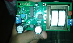
This is my first DIY build ever. Hence going slow.
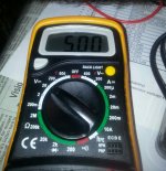
Just managed to complete the Power Supply. Checked 5-6 times and got 5.00 V reading. Guess I am good to go for DAC board.
I am planning to use Ceramic Caps at C7.
Can some one confirm whether below will work.
C1608X7R1C105K080AC - TDK - CAPACITOR CERAMIC, 1UF, 16V, X7R | element14 India[
Apart from C7 are there any major changes suggested ? Would like to build with replacement parts rather de-soldier later.
Attachments
I am planning to use Ceramic Caps at C7.
Can some one confirm whether below will work.
C1608X7R1C105K080AC - TDK - CAPACITOR CERAMIC, 1UF, 16V, X7R | element14 India
That capacitor is very small - it's size 0603. You will find size 0805 or 1206 or 1210 will be much easier to work with.
You can take a look at this thread for some advice on possible modifications to the official BOM. http://www.diyaudio.com/forums/digital-line-level/246003-modifying-subbu-v3-dac.htmlApart from C7 are there any major changes suggested ? Would like to build with replacement parts rather de-soldier later.
The things that have been officially approved by JP are the following:
1) Change C22 to a 470uf 6.3v Panasonic SEPC capacitor
2) Change C17 to a 1uf MLCC capacitor similar to the part you will use for C7
3) Change C32 to Wima MKS Polyester capacitor - size 1uf to 4.7uf. JP officially endorses using 1uf.
---Gary
Hi,
Can you suggest a compact 230v card to supply the jg buffer & get all dac fitting into a small box ?
Thanks a lot for your help,
Ps: this is for my second system as first dac is into a bigger box including raspberry.
Francois
Can you suggest a compact 230v card to supply the jg buffer & get all dac fitting into a small box ?
Thanks a lot for your help,
Ps: this is for my second system as first dac is into a bigger box including raspberry.
Francois
Just finished building my streamer using subbi dac. I put all family in front and we all agree sound is much better than my previous with other es9023. Well done to all and thanks a lot !!!
An externally hosted image should be here but it was not working when we last tested it.
With family you mean your wife and children ? I think it is very nice that they bother to listen to daddies stereo. Something not that common anymore.
Congratulations with your built and the apparent success. Please send my regards. I love that rainy sundays when everyone is doing his/her own thing and music is playing on daddies self built gear followed by cooking food together.
BTW I do think you should use adequate mounting material for mounting PCBs in a case.
Last edited:
- Home
- Source & Line
- Digital Line Level
- Build thread - building the Subbu DAC V3 SE