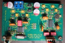
Thanks. I used indeed half of mounting holes to save time... Is this what you mean or something else ? ( please no comment on cables or case itself, I tried to lower pic resolution being ashamed of my mounting "talents") I know your work deserves better but music is there !😃
And real work was done by Korben.
And real work was done by Korben.
I used indeed half of mounting holes to save time... ....
And real work was done by Korben.
You know what Confucius said about that don't you ?
Nice soldering from Korben again.
There is no excuse for doing half work certainly when it's you building your own device yourself. Otherwise you'll end up with something like a french car 😉
Just take the time, build it straight and tidy, no chance for shorts or stuff coming loose. Add some "Kaizen" to the sauce.....improve the skills...
さようなら !
Just take the time, build it straight and tidy, no chance for shorts or stuff coming loose. Add some "Kaizen" to the sauce.....improve the skills...
さようなら !
Attachments
Last edited:

The Toyota Way goes into the Kaizen principles in great depth, don't know whether I would call it spiritual, but its a philosophy I have followed for my work ethic for many years. At one place we studied it 1 day a month for 3 years, and applied it to all aspects of design and production.
JP, you sent me off to Google land for hours on Kaizen and Six Sigma. Is it possible for you to estimate how many cycles/iterations were completed in the V3 development? Did you define them that accurately?
It were at least 30 versions (more like 50 I guess) since the first version of the DAC. I would have to check all email with Subbu to know exactly.
edit: just checked a little and I numbered every new PCB version from 2.3.4 to 2.3.5 etc. , then think of completion, wrapping up, having PCBs produced and trying out parts/testing V2.6. The ubiquitous "last changes" just before the boards were being made in their final version...
Many emails just about C17 or GND plane ..... After all this V3 came around with more or less the same routines 😉
Last edited:
Very Interesting. I just wanted an estimate. That effort and approach certainly paid off in the final product. It also helps us all understand why the development time was so lengthy. We appreciate your professionalism and dedication to high standards.
It would have been a commercial disaster the way we worked but we tried to make it the best we could make it. We emailed countlessly about every single detail.
So it really is/was about getting best possible quality with the given set of semiconductors. I am very proud that we did it like that. All this without a single quarrel or strong disagreement. I can still tell which choices were made by who.
Maybe it gives some understanding why quality of finish and dedication to quality of the builders is appreciated by me (this possibly also counts for Subbu). There is so much badly/mediocre designed stuff out there so when something comes on your path that is simply well designed then build it the best way you can.
Last edited:
Very Interesting. I just wanted an estimate. That effort and approach certainly paid off in the final product. It also helps us all understand why the development time was so lengthy. We appreciate your professionalism and dedication to high standards.
Agree with you Bob, and we learn the way of patience as well.
If you learn the life of Budha, you can notice it improves his knowledge of the way of wisdom with a Deming cycle approach...🙄 The true father of Six Sigma ????
Anyway Bob, thank you for you work about your "How to" for building it. It helps me a lot.

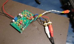
FINISHED!
Well, I've actually been finished for a while, but other stuff, plus the fear of failure has gotten in the way of getting it hooked up to test out.
SUCCESS!
For a moment there was silence, then I remembered to turn the output of my bench PSU on, haha!
You will see from the pictures that right now it is using truly ghetto connections, fear not, this was just to see if music came out. It will be going into an enclosure in the next few days.
This was my first ever smd project (yes JP, I know you advised against beginners...) and I'm really happy how it turned out. I think the main thing that helped me was getting hold of a couple of large old circuit boards and a hot air gun- practice, practice, practice. Also the tutorials from the EEVblog were a great help and gave me the confidence to tackle this in the first place.
The hardest part was definitely the oscillator. Maybe a mm or two more next time?
A big thank to Subbu, JP and everyone involved in the group buy. And also thanks to all the people contributing to the build thread. I'm looking at you, bcmbob 🙂 I don't post much, but I read just about everything. 😀
Cheers,
Mark
Some pics:
Attachments
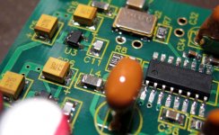
Very nice job, congratulations Mark ! Your soldering looks OK to me, not beginner status IMO. Even the Molex are used. A shining example what one can achieve if one really wishes. I stand corrected on my remarks....but also think of me being an amateur too. You are spot on about the XO. The footprint we used was OK at first but we changed to the possibility for 7x5 and 3x2 mm XO's and then changed back. I guess it was then that we choose a very narrow footprint for the XO. Just 0.5 mm more solder pad surface at each side would be enough to make it an easy task. The beta boards don't have this challenge. Your remark concerning the power switch is a known one. Still have it now and then when testing newly built boards on a bench power supply. Or no sound, suddenly thinking + an - are reversed (while you should know better...), then the thought it has blown and it turns out to be that the wrong input is chosen on the preamp. Who needs text on a front panel 😉
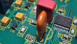
On the last picture I see some loose solder just above the text "C9". You can scratch that away with you finger nail if only to avoid a short when it comes loose in the future.
And how does it sound ? BTW you know the info on C4, C22 and C32 ?
On the last picture I see some loose solder just above the text "C9". You can scratch that away with you finger nail if only to avoid a short when it comes loose in the future.
And how does it sound ? BTW you know the info on C4, C22 and C32 ?
Last edited:
Congratulations Bike! Glad you took up the challenge.
OT, but why not.😉 Many years ago I found myself in a new job that made great money but had a little less prestige than earlier positions. Some of the guys were leaving early, so there was a big meeting where we were told immediate termination would apply next time it happened.
Next day one jerk decided the rules weren't for him and bolted about three minutes early. Everyone around me (about 40 guys) fired up and convoyed behind him to cover his dumb butt. He got sorely chastised buy the crew the next day, but I was so impressed I stayed with that team for the remainder of my career.
The diyAudio forum (most threads) has all the same rare qualities with group support plus excellent expert individual drill down on specific problems. We gain much more than we give and it's a real joy to be able to participate.😀
On the last picture I see some loose solder just above the text "C9". You can scratch that away with you finger nail if only to avoid a short when it comes loose in the future.
Aahh, um, that was where I managed to clumsily scratch off a bit of solder mask and exposed some copper track
 I thought it would be better to tin it than leave the copper uncovered. Oops!
And how does it sound ? BTW you know the info on C4, C22 and C32 ?
Well, it was just a test to see if music came out, not critical listening. So I can only say it sounds like clean music!
I think I have the caps sorted out. I know I didn't populate them all, I'll double check when I get home tonight.
Cheers,
Mark
Hi Bikeman,
is your C18 + C22 a good combo ? = no crisp in mid-treb (you can hear it on attacks as a harchness they heart the ears. Like some dynamics piano notes, saxophones, female voices in the high tones...)
It was with me with the same FP cap at C18 but 390 uF. But the C22 is a 470 SEPC withe mine. I surmise here that your C22 here paddle off maybe this crisp I had.
Anyway I had better result with the less expensive C18 of the BOM than the FP you use...always with SEPC at C22. FP cap at C22 was bad because the crisp in mid-highs was high ligthed more as well...WITh or without the "genuine soft" cap of the BOM at C18. As i already wrote above or elsewhere...
The sound have to be confortable, clear but soft without fatigues in highs or with dynamics attacks in mid and highs frequencies.
IMHO... because we have not all the same speakers or amps.
Did you go with the genuine pcb and BOM for powersupply ?
regards
Last edited:
I just added a note to the top of the first post here calling attention to the modification thread where cap selection and other topics are discussed more directly. Anyone wanting to adjust the performance/character of the V3 DAC can benefit from the information there.
Last edited:
- Home
- Source & Line
- Digital Line Level
- Build thread - building the Subbu DAC V3 SE