Hi,
the consumer level output will work because that is what the SPDIF input is designed for.
The WM8804 should tolerate the 3,3V input but I wasn't able confirm this either.
Thank you very much sir
Hi
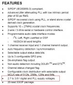
WM8804 tolerates 2.7 to 3.6v digital and PLL supply voltages 😉
From WM8804 Datasheet first page :
S/PDIF Transceivers | WM8804 | Wolfson Microelectronics
Regards
Phil
WM8804 tolerates 2.7 to 3.6v digital and PLL supply voltages 😉
From WM8804 Datasheet first page :
S/PDIF Transceivers | WM8804 | Wolfson Microelectronics
Regards
Phil
Attachments
Finally got around to connect the ES9023 DAC to play some music...
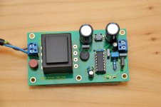
I finished my build with the parts from the GB except a few changes due
to parts I had in my bins. C2 is a 330uF Sanyo SVP, C4 is 1uF MKT //
with a 3.3uF, C21 is 10uF Wima from the bottom of the board and C22 is
0.1uF 400V PP // with a 100uF polymer for now.
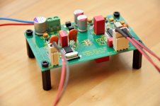
I am glad that it works trouble free (this being my first SMD DAC), and since
it is connected with flying wires and without the JG Buffer that is planned to
go with it I don't have a final verdict, yet. But after a few hours of running it
and two hours of listening I can silently utter 'holy ****'.
For such a small investment and after such a short waiting time 🙂D😀😀) this
really is a winner. In my world of audio I'd call this sounding relaxed, uncoloured,
absolutely open while revealing ALL the subtleties, and natural.
Bravo!
 to JP and Subbu
I finished my build with the parts from the GB except a few changes due
to parts I had in my bins. C2 is a 330uF Sanyo SVP, C4 is 1uF MKT //
with a 3.3uF, C21 is 10uF Wima from the bottom of the board and C22 is
0.1uF 400V PP // with a 100uF polymer for now.
I am glad that it works trouble free (this being my first SMD DAC), and since
it is connected with flying wires and without the JG Buffer that is planned to
go with it I don't have a final verdict, yet. But after a few hours of running it
and two hours of listening I can silently utter 'holy ****'.
For such a small investment and after such a short waiting time 🙂D😀😀) this
really is a winner. In my world of audio I'd call this sounding relaxed, uncoloured,
absolutely open while revealing ALL the subtleties, and natural.
Bravo!
to JP and SubbuAttachments
For such a small investment and after such a short waiting time 🙂D😀😀) this
really is a winner. In my world of audio I'd call this sounding relaxed, uncoloured,
absolutely open while revealing ALL the subtleties, and natural.
Bravo!
Thanks for the comment. I am glad you're happy with it.
....... In my world of audio I'd call this sounding relaxed, uncoloured,
absolutely open while revealing ALL the subtleties, and natural.
....
I plugged the Mini-2496 DAC back in yesterday as my V3 upgrade parts should be here presently. I have to agree - though the Mini may have a bit more body and still sounds great, Stixx's comments are right on point. I couldn't have picked a better set of words to describe the comparison. 😉
I have the housing from a guitar pedal that I though i'd put the dac pcb inside to shield it, my question is, should the metal box be connected to ground on the pcb?
Just tested the voltages, all okay it seems.
Stixx your build looks super nice and clean, can't wait to get mine playing with those fine words of how it plays 🙂
Just tested the voltages, all okay it seems.
Stixx your build looks super nice and clean, can't wait to get mine playing with those fine words of how it plays 🙂
Signor Stixx, it seems you used a tantalum cap for C17. Make that a ceramic 1 µF and the total result will be even somewhat better.
What should be the max value measured at L4?
Hi All,
I'm in need of some expert help.
I spent two nights to build the dac, but before soldering the L3 - L6 in place,
I measured the voltages.
All values seem correct (3.3 Volt) except for L4. Here it measures 4.109 volt instead of the expected 3.6Volt😱.
Is this acceptable? If not, what can be wrong? I double checked U4 to see if did something wrong with soldering, but it seems to be fine.
Thanks,
Audionootje
I would say is not OK, the U4 does not working properly or something is wrong around him.
Last edited:
Signor Stixx, it seems you used a tantalum cap for C17. Make that a ceramic 1 µF and the total result will be even somewhat better.
Monsieur Jean Paul,
yes I can try that. I have to order a ton of parts anyway for various power supplies to go with the ES9023... Thanks!
Hi All,
I'm in need of some expert help.
I spent two nights to build the dac, but before soldering the L3 - L6 in place,
I measured the voltages.
All values seem correct (3.3 Volt) except for L4. Here it measures 4.109 volt instead of the expected 3.6Volt😱.
Is this acceptable? If not, what can be wrong? I double checked U4 to see if did something wrong with soldering, but it seems to be fine.
Thanks,
Audionootje
First try to load it with a few mA. Then measure. I am not aware that MIC5205 does not work OK without load but please try with a load of 1 kOhm.
If still not 3.6V then replace it please.
Monsieur Jean Paul,
yes I can try that. I have to order a ton of parts anyway for various power supplies to go with the ES9023... Thanks!
Stixx efendim, I would love to hear more of your positive comment. A 470 µF Panasonic SEPC will do better for C22 I guess. There is a version that fits exactly on the PCB.
Last edited:
A 470 µF Panasonic SEPC will do better for C22 I guess
Jean-Paul-san, options over options. As written earlier in the thread I also have a 470uF BG-N that I could try... but I will get the bigger SEPC as well. Dank u well😉
For those who have used the Salas shunt psu, what transformer, heatsinking, etc. did you use? I can't find a thread on specific setup instructions. I'm thinking of trying out this psu on my second Subbu dac build. Thanks, all.
For those who have used the Salas shunt psu, what transformer, heatsinking, etc. did you use? I can't find a thread on specific setup instructions. I'm thinking of trying out this psu on my second Subbu dac build. Thanks, all.
Hi,
I used a 12V 30VA trasformer and dropped it to 14V with a CR before the shunt. A 9V transformer would be fine with no RC. I used Salas reflector and the chassis as heatsink. Shunt has a total consumption of 220mA.
If you use a bib, I would recommend to go for a bjt output for 5V.
Hi,
I used a 12V 30VA trasformer and dropped it to 14V with a CR before the shunt. A 9V transformer would be fine with no RC. I used Salas reflector and the chassis as heatsink. Shunt has a total consumption of 220mA.
If you use a bib, I would recommend to go for a bjt output for 5V.
Thanks, vgeorge. Yes. I plan to use bib. There's a group buy underway. Has anyone out there used the bib with the Subbu? I would be interested to know how you set it up. Kind regards.
Has anyone out there used the bib with the Subbu?
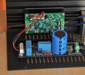
I have built the Subbu/JP-DAC 1.0 with the Salas BIB. Building it is very straightforward when you use the BIB guide that was put together by Salas.
Do you have that? Setting up the BIB for 5V just takes two LED's and a 220R resistor. Parts kits were sold by Teabag...
Attachments
I have built the Subbu/JP-DAC 1.0 with the Salas BIB. Building it is very straightforward when you use the BIB guide that was put together by Salas.
Do you have that? Setting up the BIB for 5V just takes two LED's and a 220R resistor. Parts kits were sold by Teabag...
Thanks, Stixx. I just now discovered the build guide. What transformer did you use? Regards.
First try to load it with a few mA. Then measure. I am not aware that MIC5205 does not work OK without load but please try with a load of 1 kOhm.
If still not 3.6V then replace it please.
The problem was C26. This condensator was malfunctioning. In the discovery process the U4 regulator was desoldered and.. went missing. I still had a spare 3.3 version so I soldered that in place for the time being. I know this will negativly impact the sonics, but it allows me to see if the dac is functioning. 🙄
Thanks, vgeorge. Yes. I plan to use bib. There's a group buy underway. Has anyone out there used the bib with the Subbu? I would be interested to know how you set it up. Kind regards.
I implemented BiB and Reflector, both point-2-point. Reflector was my choice.
Both are powered by 36VA 9-0-9 EI transformer and are setup to pump up approx 280ma.
I implemented BiB and Reflector, both point-2-point. Reflector was my choice.
Both are powered by 36VA 9-0-9 EI transformer and are setup to pump up approx 280ma.
Thanks, pchw. What is the reflector? Is it another variation of the Salas shunt psu? Kind regards.
- Home
- Source & Line
- Digital Line Level
- Build thread - building the Subbu DAC V3 SE