That's a very confusing way of putting it. You need to specify where the current is coming from or going to. If you're using shunt regs, you'll need to account for the losses there, which are going to be large.
Each 45V supply will need to provide 235mA to the I/V.
So:
Channel 1 +45V = 235mA
Channel 1 -45V = 235mA
Channel 2 +45V = 235mA
Channel 2 -45V = 235mA
Hope this clarifies things.
Cheers,
Owen
Each 45V supply will need to provide 235mA to the I/V.
So:
Channel 1 +45V = 235mA
Channel 1 -45V = 235mA
Channel 2 +45V = 235mA
Channel 2 -45V = 235mA
Hope this clarifies things.
Cheers,
Owen
i would really look at what pins on the sabre actually can benefit from a shunt reg, the digital core is just housekeeping, forget it, imo if you are hearing difference with shunts on this pin you are hallucinating. for me the only pins that can stand to have improvement are the analogue supplies, avcc L/R the VDD L/R and the clock. i'll post the details of the pins below, because i see over and over people asking for current ratings of each pin. this is from the ackodac user manual, so i think i'm fine with my NDA
VDD = 1.2V +/- 5% (std digital grade). ~110mA
Supplies power to the core cpu of the chip.
^standard ic reg is fine here
VDD_R = 1.2V +/- 5% (analog low noise). ~15mA
Supplies power to analog_R ref of the chip.
VDD_L = 1.2V +/- 5% (analog low noise). ~15mA
Supplies power to analog_L ref of the chip.
^these should be high quality, so shunts are good here, but only 15ma each
AVCC_R = 3.3V +/- 5% (analog low noise). ~30mA
Supplies power to analog_R output stages of the chip.
AVCC_L = 3.3V +/- 5% (analog low noise). ~30mA
^these should also be of high quality.
Supplies power to analog_L output stages of the chip.
DVCC_T = 3.3V +/- 5% (std digital grade). ~8mA
Supplies power to top pad ring of the chip
DVCC_B = 3.3V +/- 5% (std digital grade). ~8mA
Supplies power to Bottom pad ring of the chip
^^these can be any decent IC reg, the stock onboard regs are fine
Vosc = 3.3V +/- 5% (analog low noise). ~10mA
Supplies power to Crystek XO.
this again should be of high quality.
the above is for an 80mhz mclk, so just multiply by 1.25 for a 100mhz clock depending when you got your b2
Thanks to share the info qsp, I replaced Tridents 1.2V & 3.3V for SSLV Disco's version (1.2V digital core BII) Salas BiB (3.3V on board Oscillator (VDD_XO), I can say the huge improvement is to change the reg. for Oscillator including it's own dedicate psu & tx.😉
I have tried LifePo batteries instead AVCC module: I prefer AVCC module.
I have tried LifePo batteries instead AVCC module: I prefer AVCC module.
Last edited:
yep, like i said, the analogue supplies are worthwhile and make quite a difference (i consider the XO an analogue mechanism), but you are talking about replacing all of them, particularly the 1.2v 110ma VDD supply is a waste of time, money and space to use a shunt for imo. the only ones worth it are the analogue supplies i outlined above ie. avcc l/r vdd l/r (the lower current ref supplies) and the xo
Thank you qusp, it's a very good advice because as per your advice I need to reduce heat at the maximum inside the DAC.🙂
OT: Modifiying current I can use for 26 tube preamp so I can compare vs Rod Coleman heaters.
OT: Modifiying current I can use for 26 tube preamp so I can compare vs Rod Coleman heaters.
hehe no problem, thats why i mentioned it, because i figured your case temp was rising exponentially with the number of shunts in use and no point using space and adding more heat for no upgrade.
have fun!!
have fun!!
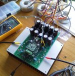
Good news and bad news:
I finish to assemble the board, and I could fire it up. I have few problems (not sure if they are problems):
1) The distortion spectrum looks like the picture attached. For all the four phases.
2) What temperature are the sink of the regulators in your built ? Mine are very hot !!
I also have a question: there are the four trimmer to set the voltage of the in pin. What voltages should I set ? I put them to zero now. Is it correct ?
Thanks,
Davide
Attachments

Good news and bad news:
I finish to assemble the board, and I could fire it up. I have few problems (not sure if they are problems):
1) The distortion spectrum looks like the picture attached. For all the four phases.
2) What temperature are the sink of the regulators in your built ? Mine are very hot !!
I also have a question: there are the four trimmer to set the voltage of the in pin. What voltages should I set ? I put them to zero now. Is it correct ?
Thanks,
Davide
remember you absolutely have to keep case temp well under 70 degrees or you will kill the sabre dac chip
Forget about the distortion spectrum. it's an effect of my silly generator at 192000. To be investigated...
D.
D.
remember you absolutely have to keep case temp well under 70 degrees or you will kill the sabre dac chip
That's OK, I am more worried about the caps of the psi.
What about the voltages of the in pins ?
D.
That's OK, I am more worried about the caps of the psi.
What about the voltages of the in pins ?
D.
Connected the BII to the I/V output pins BII measure 1.61V-1.65V
Hi Davide,
Looks great! Congrats on getting it up and running.
The regulators for the PSU do run pretty hot, but it's nothing to be concerned about. Just for the sake of safety, can you tell me what the DC voltage is at the input and output of the reg? The lower you can get that voltage drop the better, and it will depend on what transformers you have, and your line voltage.
If the differential there is way too high, you might be dissipating too much power in the regs. Ideally, for 45VDC output, you want to see about 50VDC at the input to the reg under normal line conditions. The dropout on those regs is somewhere in the ballpark of 2V.
As for the caps on the PSU, they should be fine if the temp is around 50-65C. I always buy 105C rated caps, but some of the fluffier audiophile parts only come in 85C flavours.
The voltage at the input of the I/V (or the voltage presented to the ESS DAC) should be 1.65VDC. Adjust each pot with the unit connected to the Buffalo board until you read 1.65V from each pin to GND. Check that voltage again after everything has warmed up and settled in. It's normal for it to drift a little bit with temperature.
Something does indeed look wrong with that distortion plot. There's broadband noise and what looks like harmonics of a higher frequency in there. If you've got everything working correctly you shouldn't even be able to see the second and third harmonic if your measurement floor is -110dB 🙂
Cheers,
Owen
Thanks,
I am not at home now, will make the final adjustment tomorrow. The distortion plot is strange, but these things are artifact of the signal generator, as I have them only at 196kHz. So they do not depend from the IV stage.
The transformers are custom made by sumr with 40Vac. I'll check the output tomorrow, but I think that the in-out difference is more than 2V, as I could have 50V out with no load.
In case can I increase a bit the supply voltage of the IV ? How much high I can go ? Like this I will have more heat on the sink, that will be mounted on a metal plate with a hole underneath.
Thanks,
Davide
Owen,
I found your calculation sheet for heat dissipation. I will make my measurements tomorrow, and see what's the best compromise. I will have to consider it when the cabinet is fully assembled also.
BTW, welcome back 🙂
I have also finished my headphone amp, that I use as balanced to unbalanced converter. I'll post some pictures in the thread tomorrow.
Thanks,
D.
- Home
- Source & Line
- Digital Line Level
- Build Thread - A New Take on the Classic Pass Labs D1 with an ESS Dac