Pass DIY Addict
Joined 2000
Paid Member
Hmmm... I admit to not fully understanding your statement here. In measuring the voltage input to the board, a DC measurement would reveal the voltage level of the power supply and an AC measurement would reveal the PSU ripple that is superimposed on the DC voltage. How does using an AC setting on the meter cause things to go up in smoke, presuming there is no other wiring error? I feel like I'm missing something here.your reading didn't do damage, but your setting did

Turns out I wired the cap wrong and that caused it to fail. Fixed that and now voltage is 14v (instead of 24v) and the inductor is showing 14-15v so another wiring issue I expect or something else. Taking some time to avoid more smoke and look it over again.
R
R
you did set something wrong prior to powering on ....... or you did that after power on, and was unable to spot it, having DMM in wrong function
so, culprit was in doing, not in looking throughsunglasses welding glasses
so, culprit was in doing, not in looking through
Pass DIY Addict
Joined 2000
Paid Member
Sometimes it's best to call it a day, leave it alone for a little while, and start over again. Double check EVERYTHING and compare to the schematic several times before applying power. A backward cap would certainly explain the escape of the magic smoke. The good think is that this circuit is very simple and the parts count is low. You'll get it!
Okay, took some time off to review my wiring, undid my errors and now it WORKS! Stable at 2.5v but runs pretty hot (50 deg+C). Will test with some speakers tomorrow.
Thanks Zen Mod, Monk55 and Eric for you input.
Rog
Thanks Zen Mod, Monk55 and Eric for you input.
Rog
Pass DIY Addict
Joined 2000
Paid Member
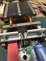
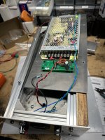
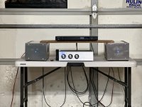
Okay, it still needs some tidying up. Plan to put in the NP 2022 Front End, redo the MeanWell HLG-480H-24 power supply input (a filter and longer cord) and it needs a front panel as well as cut an appropriate top to keep little hands out. I noticed the temporary top aluminum cover helped dissipate a fair bit of heat from the chassis. It runs pretty hot at 55 C. Not a summer amp in Sacramento for sure. Okay, here are the photos:


Monk55, yes they are. I used a Bud Box alum chassis as a "frame" for the heat sinks but cut holes out of the Bud Box to allow direct mounting to the heat sinks. Heat sinks are 17.25" long by 4.75" high and 3 1/8" deep which seemed to be adequate for the MoFo.
Rog
Rog
New MoFo greenhorn here…
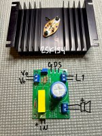
For S&Gs (sources and gates ), I want to try some 2SK134s with the boards I just got.
The sinks are undersized, but I will have fans blowing on them for testing.
I will be using 19.5VDC laptop bricks and big MOTs.
Does the attached picture check out for the board connections?
For S&Gs (sources and gates
), I want to try some 2SK134s with the boards I just got.The sinks are undersized, but I will have fans blowing on them for testing.
I will be using 19.5VDC laptop bricks and big MOTs.
Does the attached picture check out for the board connections?
Attachments
Not sure what I did wrong, but I ended up cooking the gate resistor. 
Backing off for now and will sleep on it.
Backing off for now and will sleep on it.
If the gate resistor cooked, there must be a wrong connection somewhere.
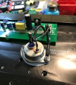
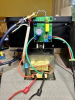
For trouble shooting, please post pictures of your amplifier showing all of the wiring. The pcb is not the MR diyAudio version so information is also needed in order to check the circuit and connections.
For trouble shooting, please post pictures of your amplifier showing all of the wiring. The pcb is not the MR diyAudio version so information is also needed in order to check the circuit and connections.
Hi MarcNot sure what I did wrong, but I ended up cooking the gate resistor.
Backing off for now and will sleep on it.
Not sure you can drive LatFet with this circuit without modifications. FYI, there’s a more recent version of this PCB (v1.1) that has the zener diode protection. See here Slowdiyer.
Hope it’s easy to troubleshoot, let’s follow Ben’s recommendations.
Eric
Burned gate resistor? Maybe parasitic oscillation. Gate/Base/Grid resistors need to be very close to the active device itself (the closer the better), not on a pcb unless the two are very close together. Hopefully your FET is not shorted / defective.
Attachments
Thanks, gents. I’m not sure what it was, but the latfet wasn’t agreeing with the setup.
At first I thought it was a loose connection on the inductor. I fixed that, jumpered the gate resistor pads on the board, and connected a new resistor at the fet gate.
Same result. Gate resistor smoked.
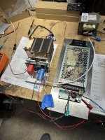
So I replaced the gate resistor on the board, attached the correct IRFP250 to a test heatsink and soldered it to the board.
No smoke. My inductor measured 60mH and 0.6R previously. 1.02V measured at the inductor produced audible distortion, so I dialed up the bias until the distortion went away. That was right about 1.4V.
The sink was getting up to 60C without a fan, so I turned the fan on. Sink staying under 40C.
It’s been running fine with my test speaker. It sounds pretty clean. I’ll use the latfets for something else.
At first I thought it was a loose connection on the inductor. I fixed that, jumpered the gate resistor pads on the board, and connected a new resistor at the fet gate.
Same result. Gate resistor smoked.
So I replaced the gate resistor on the board, attached the correct IRFP250 to a test heatsink and soldered it to the board.
No smoke. My inductor measured 60mH and 0.6R previously. 1.02V measured at the inductor produced audible distortion, so I dialed up the bias until the distortion went away. That was right about 1.4V.
The sink was getting up to 60C without a fan, so I turned the fan on. Sink staying under 40C.
It’s been running fine with my test speaker. It sounds pretty clean. I’ll use the latfets for something else.
Attachments
- Home
- Amplifiers
- Pass Labs
- Build This MoFo!