Hey dliscomb,
How do you measure the bias current?
Perhaps you already know it, but the easiest way to mesure the current is to insert a 0.1ohm / 5watt resistor(one of these ceramic types) between the PCB positive or negative supply points (does not make any difference) and measure the voltage across that same resistor while the amp is idling.
Next Ohm's law comes to the rescue, for example:
if you measure 1 volt acrros that resistor it is 1V/0.1ohm=10A (too much).
So in the case of the MoFo you would expect to see something like 150- 200mV across the 0.1ohm resistor for a 1.5 - 2A bias current.
Adjust it up or down to your liking observing the temp of the heatsinks
Off course you can measure the voltage across your Hammond choke and calculate it that way but it is not as accurate.
As PRR said above you can also insert your DMM, set to measure current (so probes are wired differently) between Mosfets Drain and PSU positive nd get the same result.
Try it and let us know.
Did the channel fail while playing, or at startup?
Tagging along with what Michael is asking...you do have a Zener in place right? I would recommend less than 20V, ~ 15V is adequate. Next, try not to turn on/off the amp from the DC side. Use an AC switch or unplug/plug in the switcher from the AC socket (human switch).
Best,
Anand.
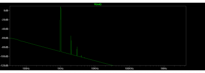
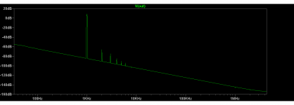
Playing with a spice Mofo model.With a 50k resistor between mosfet drain and gate gives a nice even staircase of decreasing harmonics about 10db per decade.A regular Mofo spice model does not have as even a distribution.Anyone have any comments?
Plain Mofo left window,Mofo with 50k right window.Playing with a spice Mofo model.With a 50k resistor between mosfet drain and gate gives a nice even staircase of decreasing harmonics about 10db per decade.A regular Mofo spice model does not have as even a distribution.Anyone have any comments?
Attachments
Vunce, yeah, I don't have an IR thermometer. Adding it to the list.
PRR & Stanislav, thanks for the clarification. I'll try to inline the DMM and see what numbers I get on the MOFO that's left.
Michael Rothacher, how wonderful to hear from The Creator himself! Both times the channel failed while listening.
poseidonsvoice, yes, I have a Vishay diode in place: 20v 500mW, p/n BZX55C20
Humble thanks again to everyone!
Kind regards,
Drew
If I recall correctly, Nelson Pass' writings indicated that "some 2nd harmonic was pleasing", but that higher order harmonics were not so much so. The article "Build a Class-A Amplifier" ( Audio, February 1977) claims the resulting amp has second- and third-order harmonics, but that higher order were undetectable.
If this is true, why would one want to encourage higher-order harmonics?
Even more importantly, will my old ears actually hear the difference? I guess I won't know without building it.
Kind regards,
Drew
If this is true, why would one want to encourage higher-order harmonics?
Even more importantly, will my old ears actually hear the difference? I guess I won't know without building it.
Kind regards,
Drew
Merry Christmas Mr. Rothacher. There is no denying your original design is the biggest bang for the buck but suppose you had a 30v power supply would using a cascode improve the excellent distortion figures even more ?
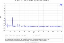
Here's the real word spectrum of a 19V channel:
The real deal,20db per decade.Thanks for the info!
I have a small CRC in my Mofo monoblocks (1000uF - 0.2ohm - 1000uF, just what
I happen to find in my parts box) I measure the voltage across the resistor to set
the bias. The small bit of capacitance should also minimize the inductor 'kick'
that can damage the mosfet if the dc cuts out suddenly.
I happen to find in my parts box) I measure the voltage across the resistor to set
the bias. The small bit of capacitance should also minimize the inductor 'kick'
that can damage the mosfet if the dc cuts out suddenly.

In this circuit, the cascode seems like it would be overkill, and might add some pentode character, though distortion could be a bit lower.
I am looking for an inductor in local market for this amp. I have provided the ratings as (common mode choke) 50mH, 2amp DC, 0.7ohm. But they are asking what type of choke/inductor, whether 3 phase choke etc.
Could you please suggest what specification (and info of type of inductor/choke) we need to provide the vendor for the inductor/choke which will be suitable for this amp
Could you please suggest what specification (and info of type of inductor/choke) we need to provide the vendor for the inductor/choke which will be suitable for this amp
Some had success using the Hammond 193V choke like this:
193V Hammond Manufacturing | Mouser Denmark
193V Hammond Manufacturing | Mouser Denmark
sarathssca,
Perhaps they want to know that you want a "filter choke". In this case it is a simple inductor, modeled as a single wire wrapped around a core.
While the model 193V that MEPER referenced is necessary for the BigMoFo, if you are building the 19V amplifier as specified in MichaelR's original article, the Hammond 193T is what you want: 193T Hammond Manufacturing | Mouser India
Perhaps a printout of those specifications will help your local shop to find something 'close enough'.
Kind regards,
Drew
Last edited:
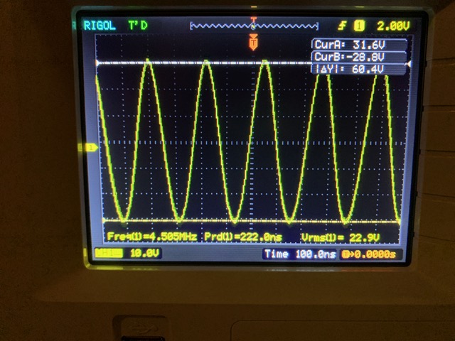
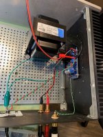
Built up a quick MoFo, seemed to work well, was reacting properly in the DC realm, listened to it for a while, VERY nice. With scope on it while looking for PSU noises found that it was oscillating quite nicely at 4.5 Mhz. (Scope shot is from inputs shorted!) Eventually this smoked a gatestopper and made the listening room smell bad... 🙄
Standard build, Prasi PCB, 24V, 193V, IRF250

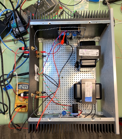
Standard build, Prasi PCB, 24V, 193V, IRF250
Attachments
Last edited:
sarathssca,
Perhaps they want to know that you want a "filter choke". In this case it is a simple inductor, modeled as a single wire wrapped around a core.
While the model 193V that MEPER referenced is necessary for the BigMoFo, if you are building the 19V amplifier as specified in MichaelR's original article, the Hammond 193T is what you want: 193T Hammond Manufacturing | Mouser India
Perhaps a printout of those specifications will help your local shop to find something 'close enough'.
Kind regards,
Drew
Triad C-56U,35mH 2 Amps $14.14 USD Mouser India
Built up a quick MoFo, seemed to work well, was reacting properly in the DC realm, listened to it for a while, VERY nice. With scope on it while looking for PSU noises found that it was oscillating quite nicely at 4.5 Mhz. (Scope shot is from inputs shorted!) Eventually this smoked a gatestopper and made the listening room smell bad... 🙄
Standard build, Prasi PCB, 24V, 193V, IRF250,............
besides increasing gate stopper slightly , you can try putting some tiny bugger cap from G to D
start with 100p , end when you cure it , check highs
or , before everything else , you can shunt bias pot wiper to gnd , say with 1uF solid
- Home
- Amplifiers
- Pass Labs
- Build This MoFo!