I originally printed them on my 3D printer to get a feel and tweak the design and dimensions.
Looks incredible in Al. Very impressive that you pulled it from a solid block.
Did you have a chance to try the PLA version? It would probably be sufficient to test the shape and driver combination.
Hi folks, one of the reason I posted this project here - beside sharing the fun - is to ask for some advise on the crossover design.
With the mechanical part of the build almost done, I'll be turning my attention to the cross-over design and realization.
IMO you should measure how your drivers perform in this cabinet. Nothing wrong in starting with a stock $30 XO as a protection device for your expensive $300 tweeters but it probably won't be optimal for your final design. Using Xsim (or asking here) after measurements is a good idea. Measuring your drivers in this cabinet with something like REW + a UMIK mic would let you know how complex the XO + compensation is going to be and to realize its full potential. It will also help you decide on active/passive and amplifiers as well.
Last burning question, the original design from B&O is vented with a port in the front of the speaker (there is a funnel connecting the opening below the bottom mid range and the front of the speaker - see first post for picture). Do you think this is a good idea - I have a larger volume to start with but I can easily 3D print a port as well.
Based on the driver and it's chamber volume you could use (or ask here) for a simulation (Hornresp) to at least get an idea of the expected performance then make your choice of whether to port it.
P.S. I can't stop looking at it. 😀
I'm surprised I never saw this thread.
I hate to be That Guy, but I'm afraid that tweeter won't work: when the diameter of the tweeter exceeds about 3/4", you get a dip in the high frequency response.
I've posted an embarrassing amount of threads on how to build these things, and even put myself in the hospital trying to make one :O (Cut my thumb in half trying to make these out of wood.)
Here's the Beolab 18 specs - note the use of a 3/4" tweeter, for the reasons I describe : Beolab 18 Speakers - Iconic & Exceptional wireless sound | B&O | Bang & Olufsen
Here's the Beolab 50 specs - despite being a larger and more powerful speaker than the 18, it also uses a 3/4" tweeter:
BeoLab 50 - High End Floor Loudspeaker | Bang & Olufsen
On the upside, you MAY be able to use the lenses, but with a different tweeter. Try an SB19, I've used it on many lenses, with no issues.
Last edited:
Thanks for the info Patrick, I'd like to learn more about the frequency dip for diameters > 3/4".
I always thought that the dimensions should scale but I guess there is a dependency to the wavelength.
I did "reverse engineer" the speakers form the BeoLab18 and did notice that the tweeter was 3/4" and the midrange 4".
If you could share some documentation on this I'd be very grateful
Happy Holidays !
Pierre
I'm surprised I never saw this thread.
I hate to be That Guy, but I'm afraid that tweeter won't work: when the diameter of the tweeter exceeds about 3/4", you get a dip in the high frequency response.
I've posted an embarrassing amount of threads on how to build these things, and even put myself in the hospital trying to make one :O (Cut my thumb in half trying to make these out of wood.)
Here's the Beolab 18 specs - note the use of a 3/4" tweeter, for the reasons I describe : Beolab 18 Speakers - Iconic & Exceptional wireless sound | B&O | Bang & Olufsen
Here's the Beolab 50 specs - despite being a larger and more powerful speaker than the 18, it also uses a 3/4" tweeter:
BeoLab 50 - High End Floor Loudspeaker | Bang & Olufsen
On the upside, you MAY be able to use the lenses, but with a different tweeter. Try an SB19, I've used it on many lenses, with no issues.
Looks incredible in Al. Very impressive that you pulled it from a solid block.
Did you have a chance to try the PLA version? It would probably be sufficient to test the shape and driver combination.
Yes I used the ABS version to test the geometry but I always felt like the lack of mass didn't give the acoustic lens a fair chance - I honestly can't wait to try them now 🙂
IMO you should measure how your drivers perform in this cabinet. Nothing wrong in starting with a stock $30 XO as a protection device for your expensive $300 tweeters but it probably won't be optimal for your final design. Using Xsim (or asking here) after measurements is a good idea. Measuring your drivers in this cabinet with something like REW + a UMIK mic would let you know how complex the XO + compensation is going to be and to realize its full potential. It will also help you decide on active/passive and amplifiers as well.
I'll be asking around for someone who can help me measure these drivers and I agree I ultimately want to build my own crossover but I felt like I should have something to start with
Based on the driver and it's chamber volume you could use (or ask here) for a simulation (Hornresp) to at least get an idea of the expected performance then make your choice of whether to port it.
P.S. I can't stop looking at it. 😀
Thanks a lot for the info - another great resource I need to look into, you guys are awesome !
Impressive work!
Many thanks - I don't know how they will sound but I sure like the way they look and will always be an improvement from my beat up MTM pair I built 10 years ago - with the help of this very community 🙂
Thanks for the info Patrick, I'd like to learn more about the frequency dip for diameters > 3/4".
I always thought that the dimensions should scale but I guess there is a dependency to the wavelength.
I did "reverse engineer" the speakers form the BeoLab18 and did notice that the tweeter was 3/4" and the midrange 4".
If you could share some documentation on this I'd be very grateful
Happy Holidays !
Pierre
It DOES scale: basically the larger the diaphragm is, the lower in frequency the dip is. A 3/4" tweeter will have a dip, but it's above 20khz.
I make my lenses with a 1" throat. That way, I can use them with a 3/4" tweeter, a 1" compression driver, a 7/8" tweeter, etc...
I'm stunned! Amazing work you have done here! You really take the DIY to the next level…
My hats off 🙂
My hats off 🙂
First attempt at CrossOver design - inputs welcome
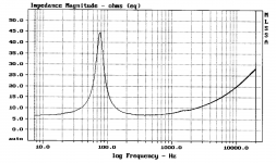
So I have tried my hand at a crossover design, I started by studying the specs of the drivers I bought:
https://www.parts-express.com/pedocs/specs/287-032-morel-em-428-specifications.pdf
and
https://www.parts-express.com/pedocs/specs/277-070-morel-et-338-specifications.pdf
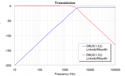
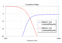
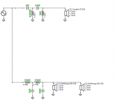
I'm going to start with a simple Linkwitz & Riley 4th order and then added a resistor network to bring the sensitivity to the same level (had to lower the tweeters by 5dB (Bummer)
Finally I added a series notch on the tweeters.
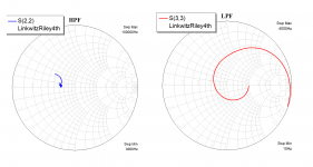
You can see the transmission response of the low pass and high pass branches of the crossover. I'm pretty happy with the gain flatness and crossover point right around 3kHz but not so much about the return loss on each branch, I plotted the low pass (mid-range/woofer) in DC-3KHz freq range and the tweeter in the 3kHz-20KHz range and I was surprised to see so much impedance variation.
Does anyone knows a way to find and load the actual speaker impedance ? The smith charts are actually normalized to 8 and 4 Ohms respectively.
So I have tried my hand at a crossover design, I started by studying the specs of the drivers I bought:
https://www.parts-express.com/pedocs/specs/287-032-morel-em-428-specifications.pdf
and
https://www.parts-express.com/pedocs/specs/277-070-morel-et-338-specifications.pdf
I'm going to start with a simple Linkwitz & Riley 4th order and then added a resistor network to bring the sensitivity to the same level (had to lower the tweeters by 5dB (Bummer)
Finally I added a series notch on the tweeters.
You can see the transmission response of the low pass and high pass branches of the crossover. I'm pretty happy with the gain flatness and crossover point right around 3kHz but not so much about the return loss on each branch, I plotted the low pass (mid-range/woofer) in DC-3KHz freq range and the tweeter in the 3kHz-20KHz range and I was surprised to see so much impedance variation.
Does anyone knows a way to find and load the actual speaker impedance ? The smith charts are actually normalized to 8 and 4 Ohms respectively.
Attachments
-
![Untitled Project - Microwave Office - [LinkwitzRiley4th]_3.png](/community/data/attachments/662/662300-5bcfe057ee6e579526e42f457a3e778a.jpg?hash=W8_gV-5uV5) Untitled Project - Microwave Office - [LinkwitzRiley4th]_3.png53.9 KB · Views: 468
Untitled Project - Microwave Office - [LinkwitzRiley4th]_3.png53.9 KB · Views: 468 -
 PrtScr capture_5.png62.7 KB · Views: 474
 -
 PrtScr capture_6.png33.9 KB · Views: 448
 -
 PrtScr capture_7.png82.7 KB · Views: 451
 -
![Untitled Project - Microwave Office - [LinkwitzRiley4th].png](/community/data/attachments/662/662339-de24767dac1e9277bf756ff658c36263.jpg?hash=3iR2fawekn) Untitled Project - Microwave Office - [LinkwitzRiley4th].png104.9 KB · Views: 448
Untitled Project - Microwave Office - [LinkwitzRiley4th].png104.9 KB · Views: 448 -
 Specs Sheets Midrange.xls - 287-032-morel-em-428-specifications.pdf - Mozilla Firefox.png419.8 KB · Views: 123
You need to look up Xsim, and get familiar with that program. It's free, and you can use real or traced plots.
Later,
Wolf
Later,
Wolf
So I have tried my hand at a crossover design, I started by studying the specs of the drivers I bought:
https://www.parts-express.com/pedocs/specs/287-032-morel-em-428-specifications.pdf
and
https://www.parts-express.com/pedocs/specs/277-070-morel-et-338-specifications.pdf
I'm going to start with a simple Linkwitz & Riley 4th order and then added a resistor network to bring the sensitivity to the same level (had to lower the tweeters by 5dB (Bummer)
Finally I added a series notch on the tweeters.
You can see the transmission response of the low pass and high pass branches of the crossover. I'm pretty happy with the gain flatness and crossover point right around 3kHz but not so much about the return loss on each branch, I plotted the low pass (mid-range/woofer) in DC-3KHz freq range and the tweeter in the 3kHz-20KHz range and I was surprised to see so much impedance variation.
Does anyone knows a way to find and load the actual speaker impedance ? The smith charts are actually normalized to 8 and 4 Ohms respectively.
What program is that ? Spice? Why do you need a Smith chart?
If you use Xsim (free, easy to drive, and purpose specific) you can right click the driver symbol and add "FRD" and "ZMA" files to the driver to reflect its actual output and impedance. The manufacturer usually supplies them, or use 3rd party published measurements, or you could extract from graphs using trace program, or you could measure them using REW + simple resistor fixture.
Last edited:
Cross Over update
First of all I want to thank everyone who helped me find the right resources. I played a bit with Xsim but ultimately used VirtuixCAD.
I used the SPL trace tool to digitize the frequency and impedance responses but found the result not so accurate. I reverted to my trusty Engauge Digitizer to digitize these curves (I have attached them for reference if anyone is interested)
Then I proceeded to designing the crossover - ended up with a 4th order L&R like before but no sensitivity adaptation or series notch.
I look forward to your comments - I do like the flatness of the directivity but the crossover itself looks a bit lossy to my taste
Attachments
Last edited:
I remember my first loudspeaker project:
I purchased a software program called CALSOD, invested weeks in learning it, then carefully designed the crossover based on the principles described in Dickason's book. (https://www.amazon.com/Loudspeaker-Design-Cookbook-Vance-Dickason/dp/1882580338)
Then I invested about $150 in quality parts from Madisound, and dutifully waited for them to arrive.
This was a lot of money and effort, I was a teenager making $7000 per year.
And it sounded AWFUL.
Basically I didn't understand that the response of the loudspeaker will depend on the distance between the elements, and the shape of the baffle.
@pagirgard, I hate to be That Guy (again) but you can't design a crossover based on response curves from a spec sheet. It won't work. You have to measure the drivers with a microphone in their enclosure.
Understood - I'm just looking for a starting point - I have yet to find someone who can help me measure properly the speakers once the enclosure is done (almost now) and more importantly there are still several parameters one could tweak on the enclosure (volume for the mid, vent port length and geometry,...) so ultimately this is an optimization loop and one has to start somewhere...
I remember my first loudspeaker project:
I purchased a software program called CALSOD, invested weeks in learning it, then carefully designed the crossover based on the principles described in Dickason's book. (Loudspeaker Design Cookbook: Vance Dickason: 9781882580330: Amazon.com: Books)
Then I invested about $150 in quality parts from Madisound, and dutifully waited for them to arrive.
This was a lot of money and effort, I was a teenager making $7000 per year.
And it sounded AWFUL.
Basically I didn't understand that the response of the loudspeaker will depend on the distance between the elements, and the shape of the baffle.
@pagirgard, I hate to be That Guy (again) but you can't design a crossover based on response curves from a spec sheet. It won't work. You have to measure the drivers with a microphone in their enclosure.
You have the driver FRD+ZMA files and VituixCAD has a box and baffle modeler for the LF / MF. Whats left is that HF acoustic lense that would require measurement and possibly more elaborate compensation. As you say, it is an iterative process, some decisions need to be made before you can even start measuring. You could characterize that HF lense using a simple cheap stock XO or even a series cap (to protect your driver) and a measurement mic. There will be plenty of people on this site that can offer measurement help and REW is very popular.
I also think you can get close on iteration#1 with VituixCAD and I'm sure you're aware of the authors thread VituixCAD where you can get some answers.
There is also the hybrid option of getting the electrical XO working as best you can on iteration#1 using Vituix. Then using active EQ to do the remaining speaker and room corrections on iteration#2+ using actual measurements. Once you see what corrections are required you can decide if/how they can be finally implemented. Typically its saggy bass (BSC miscalc) and a few mystery resonant bumps (notch filters).
Last edited:
4th order is probably over the top, 2nd order LR would be OK, however if you wish to use the 2nd woofer to take into account baffle step, and for 5" width that's ~ 900Hz, a series Xover might be more cost effective.
Beautiful! This is what DIY is all about, for someone to learn all the aspects of making your own speakers. Not just everyday run of the mill speakers, but some very unique and modern art masterpieces.
It makes me motivated to work on all my projects, so thank you!
It makes me motivated to work on all my projects, so thank you!
If you update your profile with your location, it might be easier to find someone to help you take measurements.
If you update your profile with your location, it might be easier to find someone to help you take measurements.
I just did, thanks for the info 🙂
FYI, @gaga did a simulation of an acoustic lense at Cloning a $3200 Speaker for $400 . Worth having a look at to compare to your lense.
- Home
- Loudspeakers
- Multi-Way
- Build log : DIY Beolab 18