FYI, @gaga did a simulation of an acoustic lense at Cloning a $3200 Speaker for $400 . Worth having a look at to compare to your lense.
thanks a lot for the link - a very interesting post indeed - I looked into the ABEC but the script intensive software seems to have a very steep learning curve. We use Comsol at work so I'm going to ask a colleague to run a sim for some beer 🙂
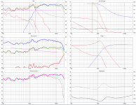
I'm very eager to see the frequency dip Patrick has mentioned
Right now I've been playing with VituixCAD to take into account the enclosure in the mid range, started the CAD for the port (complex shape from cylinder to rectangle horn) and in the shop putting some lacquer on the front wood blades - stay tuned for updates 🙂
Quite a lot to learn - thanks again for sharing !
Pierre
If you update your profile with your location, it might be easier to find someone to help you take measurements.
To anyone reading this post in the Orlando FL area, if you can measure the speakers in their enclosure I'll trade you for a project of your own in my shop (woodworking, fabrication, CNC, lathe, ....)
Happy New year everyone

Crossover design and build
Hi everyone,
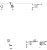
I took a stab at reducing the order of the crossover as mentioned in comments and settle with a 2nd order - to start with.
I realize that this is an educated shot in the dark at this point but I plan to build, test, tweak both the crossovers and the speakers internals until I'm happy with the sound.
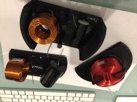
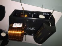
So after some sims I ordered the components and instead of building a PCB or directly solder the components like I did in the past. I 3D printed some boards: one for the tweeter C-L , one for the Woofers L-C, and one for the big inductor in between the woofers.
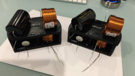
The boards have the shape of the cylinder and the fit perfectly at the bottom of the speakers
Soldering was done by a friend with much steadier hands.
I use crimping connectors to make the assembly and tweaking a bit easier down the road
Hi everyone,
I took a stab at reducing the order of the crossover as mentioned in comments and settle with a 2nd order - to start with.
I realize that this is an educated shot in the dark at this point but I plan to build, test, tweak both the crossovers and the speakers internals until I'm happy with the sound.
So after some sims I ordered the components and instead of building a PCB or directly solder the components like I did in the past. I 3D printed some boards: one for the tweeter C-L , one for the Woofers L-C, and one for the big inductor in between the woofers.
The boards have the shape of the cylinder and the fit perfectly at the bottom of the speakers
Soldering was done by a friend with much steadier hands.
I use crimping connectors to make the assembly and tweaking a bit easier down the road
Attachments
And the horns/ports now
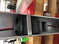
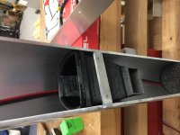
I 3D printed brackets that allow for cable management (2 notches in the back) and that will support the horns/ports for venting the woofer area in the front of the speaker. The length and area of the horn was calculated using the enclosure tool in VituixCAD tool
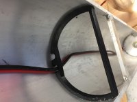
I then modeled the horn/port in Fusion 360 aiming for a smooth transition between the rectangular section of the front port and the "D" shape section of the internal speaker.
It took several printing iteration to get a smooth surface finish inside the tubes. The outside is still pretty rough but it won't affect the function of the part.
The horns/ports then slide onto the brackets and the hole assembly can slide up and down to adjust the internal volume of the woofers cavity
I cut the opening of the front panels in the CNC but forgot to take pictures - sorry
Next step is assembly and test - I just received my calibrated Microphone and learning REW 🙂
I 3D printed brackets that allow for cable management (2 notches in the back) and that will support the horns/ports for venting the woofer area in the front of the speaker. The length and area of the horn was calculated using the enclosure tool in VituixCAD tool
I then modeled the horn/port in Fusion 360 aiming for a smooth transition between the rectangular section of the front port and the "D" shape section of the internal speaker.
It took several printing iteration to get a smooth surface finish inside the tubes. The outside is still pretty rough but it won't affect the function of the part.
The horns/ports then slide onto the brackets and the hole assembly can slide up and down to adjust the internal volume of the woofers cavity
I cut the opening of the front panels in the CNC but forgot to take pictures - sorry
Next step is assembly and test - I just received my calibrated Microphone and learning REW 🙂
Attachments

awesome project! any news on the progress?
I am looking into making accoustic lenses ala Beolab 18 my self for another speaker project. Only have 3D printing readily available as a tool. no CNC.
I am looking into making accoustic lenses ala Beolab 18 my self for another speaker project. Only have 3D printing readily available as a tool. no CNC.
Last edited: