You can get -40dB easily, and even -60dB with a well designed notch filter. They were doing this stuff in the 1930s.
Um....sure, but 67kHz SCAs are frequency modulated with a deviation of 3-5kHz. Total bandwidth of those SCAs is wider yet. Injection is below 10% already, so you don't need a deep notch, you need a wide one with steep sides and flat group delay below 57kHz.
Have fun with that with 1930s technology.
ejp, no confusion here.
I've always been fully aware that you are not the OP. However, as the OP did start the thread, I presume he's still reading it, and as it's a public forum, I also would have to assume others are too.
You will know if I have something to say just to you. It would be in the form of a PM.
I've always been fully aware that you are not the OP. However, as the OP did start the thread, I presume he's still reading it, and as it's a public forum, I also would have to assume others are too.
You will know if I have something to say just to you. It would be in the form of a PM.
So why are you accusing me of 'just throw[ing] filters anywhere'? It's the OP doing that, not me. I'm the one who tried to stop him.
My point really is, any 67kHz filter at all is a compromise. Its applying one bandaid on top of another. The 1960s solution wasn't really all that good.
If a contemporary demodulator is used, no filter is required because the products that intermod won't be there in the first place. And all performance is better.
I frankly am puzzled by the project in the first place, why would anyone want to use such a primitive design just to utilize a tube? And if tube usage is the goal, why is it the demod? Why not just drop the tubes in the output stage and use a modern stereo demod without all these issues?
I'll have to learn more about contemporary demodulators. And forget about what I'm doing currently. Anywhere I can read up on contemporary demodulators? Haven't found anything with enough details. It's a learning experience.
Having scanned the thread I have not seen an actual practical use mentioned by way of naming any particular mono tuner to which a multiplex - as discussed - would be applied.
My main interest is in adding stereo to the good old UK Leak Troughline II & III tuners. Has anyone built a decent chip based Multiplex unit for these Tuners?
My main interest is in adding stereo to the good old UK Leak Troughline II & III tuners. Has anyone built a decent chip based Multiplex unit for these Tuners?
brianco,
Check fmmpx.com
wa2wise,
If you want to dig deeper into MPX, get a Panasonic/Matsushita VP-7633/35/37, Meguro MSG-211, or similar MPX generator. Right now you are just guessing what is happening. The ear is not exactly a very accurate test equipment when it comes to distinguishing the source of the birdies.
PLL MPX ICs that use internal 50% duty cycle square switching are inherently immune to SCA with typical 80dB rejection.
I have measured a lot of FM stereo tuners and analyzed their schematics. A lot of the information I found are not mentioned explicitly on textbooks.
brianco,
Check fmmpx.com
...
PLL MPX ICs that use internal 50% duty cycle square switching are inherently immune to SCA with typical 80dB rejection.
.
I thought 🙂 I was doing 50% duty cycle switching, grabbing the switch signal off the chip I'm using and making the tube do the switching. I'm not even sure I'm getting SCA interference... Gotta do more listening, and such...
Check the Sansui TU-9900 schematic. It uses an early generation of PLL MPX IC as its 38kHz MPX switching source. MPX decoding is done with the diode matrix. It might give you an idea on where to get your 38kHz waveform instead.
The TU-9900 is not immune to 67kHz SCA, 78kHz, 114kHz, 152kHz and 190kHz AM detection, all are within +/-15kHz of the 38kHz odd and even harmonics. It is immune to 57kHz RDS birdies due to its 19kHz pilot filter.
The TU-9900 is not immune to 67kHz SCA, 78kHz, 114kHz, 152kHz and 190kHz AM detection, all are within +/-15kHz of the 38kHz odd and even harmonics. It is immune to 57kHz RDS birdies due to its 19kHz pilot filter.
Dude, this isn't all about you.So why are you accusing me of 'just throw[ing] filters anywhere'? It's the OP doing that, not me. I'm the one who tried to stop him.
No, square wave switching by itself is the problem. What they do to clean it up is the solution. Non-square wave demods avoid the problem.PLL MPX ICs that use internal 50% duty cycle square switching are inherently immune to SCA with typical 80dB rejection.
No, square wave switching by itself is the problem. What they do to clean it up is the solution. Non-square wave demods avoid the problem.
Look up the datasheets of some common PLL MPX ICs that employ 50% duty-cycle square wave switching: HA1196, LM1310/BA1310, HA11223, uPC1197
The LA3450 and TCA4500/LM4500 don’t employ 50% duty cycle square wave switching that is why I excluded them. Look up the schematic of the Tandberg 3001A. It uses a similar scheme as these 2 PLL MPX ICs.
FM stereo tuners that employ these 50% duty-cycle ICs or similar ones directly as MPX decoders have no SCA post detection filters since they don’t need one.
I’m actively involved with a multiplex stereo decoder design meant to replace the Sansui TU-9900 MPX board. I have designed and built my own passive LC post-detection filter specifically for eliminating IBOC self-noise that is a problem in North America. Along the same lines, I also have a very flat (0/-0.5dB) MPX filter with deep notches at 19kHz & 38kHz. I have a lifetime supply of the high end PLL MPX decoder ICs that will be used with these custom hand-built LC filters.
We can talk about this topic all day but if your reality is different from mine then there is no way of having any productive conversation, I will just ignore your posts moving forward. Life is short.
Last edited:
Look up the datasheets of some common PLL MPX ICs that employ 50% duty-cycle square wave switching: HA1196, LM1310/BA1310, HA11223, uPC1197
The LA3450 and TCA4500/LM4500 don’t employ 50% duty cycle square wave switching that is why I excluded them. Look up the schematic of the Tandberg 3001A. It uses a similar scheme as these 2 PLL MPX ICs.
FM stereo tuners that employ these 50% duty-cycle ICs or similar ones directly as MPX decoders have no SCA post detection filters since they don’t need one.
I’m actively involved with a multiplex stereo decoder design meant to replace the Sansui TU-9900 MPX board. I have designed and built my own passive LC post-detection filter specifically for eliminating IBOC self-noise that is a problem in North America. Along the same lines, I also have a very flat (0/-0.5dB) MPX filter with deep notches at 19kHz & 38kHz. I have a lifetime supply of the high end PLL MPX decoder ICs that will be used with these custom hand-built LC filters.
We can talk about this topic all day but if your reality is different from mine then there is no way of having any productive conversation, I will just ignore your posts moving forward. Life is short.
I will defer to the self-proclaimed expert. As you said, life is short.
I spent quite a few years dealing with SCA squeal on both the transmission and reception side. Initially, the blame was equal on both. Then in the early 1980s the SCA intermod problem was solved for the transmission side, but we had birdies in receivers for decades beyond that. Because the transmission side was now clean, I blamed the demod. I might be wrong. IIR, second harmonic of 38=76, 67kHz modulated +/-5kHz puts IMD products between 4 and 9kHz. And with mod sidebands of the 38kHz dsbsc as low as 23kHz, you could get IMD products with the 67kHz carrier as low as 2kHz. The "cure" back then was to soft switch at 38K, some tried digital stepping, and improved linearity of the total baseband.
But hey, if the new chips cleaned all that up, great.
Look up the datasheets of some common PLL MPX ICs that employ 50% duty-cycle square wave switching: HA1196, LM1310/BA1310, HA11223, uPC1197
Found datasheets:
This one shows the internal schematic of this chip CA1310 Datasheet Archive lm1310%20applications datasheet download
https://www.digchip.com/datasheets/download_datasheet.php?id=1447463&part-number=UPC1197C
In Japanese: https://www.digchip.com/datasheets/download_datasheet.php?id=2888323&part-number=HA1196
More Japanese: BA1310 datasheet
Thing is, so far most I see are block diagrams without any details. The one with the schematic may show more secrets. 😀

This is pretty much the same approach as the one used by Warren Lane (I believe from Australia).This is a FM MPX stereo decoder that uses a stereo chip to acquire the 38KHz switching waveform, and applies that to a "TV" tube that switches on and off the composite audio (which carries both the mono and the L-R difference signals) to produce left and right audio outputs. Idea is to use the chip to get a synchronized switching waveform. And the tube handles the audio signal that will go to your audio amplifier.
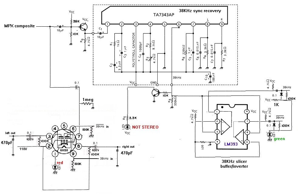
First thing is to find a chip that produces a 38KHz switching waveform. Turns out most of these stereo decoder chips don't provide that, keeping this signal inside itself. Some will provide 19KHz, but that's not useful. With my selected chip datasheet TA7343 I can get the 38KHz signal, but only if I don't have it directly drive an indicator LED. Doing that disables the chip's stereo demod section, but I'm not using that here. I found that when this chip loses lock on the stereo pilot signal, this 38KHz output pin goes much higher in voltage, thus I used a buffer circuit to light a "not stereo" LED indicator when that happens. The FM radio station essentially MUXes the left and the right channels by alternating the left and right audio signals at 38KHz rate. Making a sequence of L, R, L, R, etc at this 38KHz rate (time division multiplex) And my circuit recreates this 38KHz switching signal and essentially deMUXes the left from the right. The 6HS8 is a tube meant for color TV work, where this tube splits apart chroma information (which is also a MUXed signal of R-Y and B-Y chroma signals). In my circuit, each grid 3 has a square wave at the 38KHz rate that allows (when near +2V) its audio channel to get to its respective plate, or when this grid goes about -5V negative, cuts off the audio (disabling the audio that belongs to the other channel from reaching this plate). I used an LED to create a fixed bias for this tube, so these levels would always work). The LM393 dual comparitor chip produces 2 38KHz square waves, one inverted (it's essentially a data slicer). These square waves feed the grid 3's after passign thru a "DC restore" circuit that sets the voltage range of these square waves to levels the tube wants (also if stereo lock is lost, this circuit will clamp both signals to an "on" level, thus passing audio to both outputs). Otherwise, the comparitor chip will make a positive level on one output and a negative level on the other, thus cutting off one of the outputs.
I appear to be getting good channel separation, but no, I haven't figured out which channel is the left, and which is the right, just yet! 😀
He used a couple of ICs to implement a PLL to recover the 19kHz signal and then, via a few more ICs he constructed the 38kHz signal.
I remember that a comparator (maybe the same one?) was used as well as some 4046s and the like.
He also had a vale audio output stage. I don't think any discrete transistors were used - only ICs, the sheet-beam tube and a few of triodes on the input and output.
This was (if I recall correctly) shared with me via the Yahoo Groups (now closed) H.J.Leak group. Unfortunately, I have not kept in touch with him since. It has now been ported over to ioGroups. There's no relevant information about this circuit there. If I can find anything in my basement/files/old pc I will try to share it but don't hold your breath (it was more than 20 years ago).
There is some information on the history of MPX ICs provided in this antiqueradios.com thread:Found datasheets:
This one shows the internal schematic of this chip CA1310 Datasheet Archive lm1310%20applications datasheet download
https://www.digchip.com/datasheets/download_datasheet.php?id=1447463&part-number=UPC1197C
In Japanese: https://www.digchip.com/datasheets/download_datasheet.php?id=2888323&part-number=HA1196
More Japanese: BA1310 datasheet
Thing is, so far most I see are block diagrams without any details. The one with the schematic may show more secrets. 😀
https://antiqueradios.com/forums/viewtopic.php?f=13&t=359796
by forum member robertjt. It is stated that the LM1310 and LM1800 ICs were dating from the seventies and were intended for car use. As such they did not exhibit particularly low noise, nor were intended for use in high fidelity equipment but that the UPC1197 instead was designed with higher specifications. Mashusita AN362 Rohm BA1320 Hitachi HA12026 Sanyo LA3361 and the NEC UPC1197 are Japanese clones of UPC1197. Perhaps the LM4700 is a National clone.
Some specifications etc. are given in the thread.
False. LM1310 = MC1310, and those were used in all kinds of hifi gear, by Marantz, Harmon-Kardon, Tandberg, ...the LM1310 and LM1800 ICs were dating from the seventies and were intended for car use. As such they did not exhibit particularly low noise, nor were intended for use in high fidelity equipment
He has perpetrated many other mistakes there, for example "so you need 150khz of IF bandwidth to recover 100% of the audio.". This is flat-out wrong. You need at least 240kHz to recover stereo and 180kHz to recover mono. He is confusing FM deviation with the sideband spread, which is considerably greater. Bessel functions. The point was debated with robertj in that forum but he never appeared to understand.
He further exhibits that he doesn't know what he's talking about when he discusses limiting, AGC, and clipping. His statement "the FM detector stage is supposed to reject AM and noise found on the carrier" is a statement of the impossible, unless a ratio detector is used, and even then there is usually a limiter stage preceding the detector, doing exactly the job he ascribes to the detector. He's wrong about 53kHz bandwidth as well, as appears in the forum, and various other things.
Last edited:
ejp I see what you mean. I read all of robertjt's comments and the responses to them after reading your post.
The second comment where the IF frequencies etc. are mentioned makes no sense, I agree.
Re. the FM bandwidth vs. deviation, in robertjt's defence, I think its easy to forget the difference between the two (i.e. as far as a practical target bandwidth is concerned) when some time has elapsed since the last time one has visited the theory. Everything read from a public forum such as this one should be taken with a grain of salt as everyone's knowledge is limited to some extent or another.
But I think that for the rest of his comments, it's a mixture of confused concepts and a rather casual usage of English. E.g. where he mentions discriminator along with limiting, as you also admit, there is this added function of the discriminator (up to a point), i.e. disturbance rejection. As for the limiter stage, he acknowledges it at a later comment. Also, I believe that perhaps the radios he has in mind are the cheaper fist attempts at valve FM receivers where perhaps economy was achieved by skipping a stage or two or combining them into one. I have never seen any such designs, however, so this is just a wild guess.
Do you have any preference over IC MPX decoders? Are there any designs which are clearly of the budget variety in your opinion? I would see no reason for this to be the case but I am curious never-the-less.
I admit that bar circuit improvements or alternative decoding methods, it's impossible to make a direct comparison, like-for-like, of IC MPX decoders as that would be affected by implementation and besides being costly, it would be very time consuming. I think no-one has done it (except maybe researchers), i.e. compared a different decoder stage with all else the same (FM tuner, power supply and audio stage).
LM4500. See http://www.fmmpx.com. Ive built about 20 of these into various hifi tuners, and the customers rave. I've tried a few other chips, but they are mostly very tied to a prior IF chip from the same stable.Do you have any preference over IC MPX decoders?
I don't really agree with the proposition that there even are budget FM chips. The car radio application is actually extremely demanding, and S/N ratios better than FM itself are easily achieved: no reason to economise there.
I don't agree about forgetting the theory either. Once you've encountered the Bessel functions, never forgotten. I did them at universityi N 1973 and recognized them immediately in FM theory 35 years later. I think it's really.a case of a lot of half-baked knowledge not properly assimilated.
- Home
- Source & Line
- Analogue Source
- Build a FM stereo decoder using chip and tube