I tried that, turns out the transistor wasn't turning on hard enough to black out the LED. It just dimmed it.

You need to get a lot more serious about filtering. First-order will not cut it. You need a 19KH pilot tone filter, a 38KHz notch filter, an SCA trap, and an accurate implementation of de-emphasis. You can accomplish the first three reasonably well with a 3rd-order or M-derived filter.
You need to get a lot more serious about filtering. ...
I know, I'll have to look on line to find good filters that won't mess up the group delay of the MPX signal.
The group delay only matters going into the MPX. Everything I mentioned except SCA needs be filtered after it.
The group delay only matters going into the MPX. Everything I mentioned except SCA needs be filtered after it.
Duh, of course. 😀 Didn't think of that, another brain fart on my part. That would make things easier.
Tried doing a Bessel low pass filter, with 7 orders. Bessel filters have good group delay characteristics. Which I'd want, so the timing of the left and right signals don't get smeared in time. Stopbands are weaker than other filters, but I figured that it would be enough. Couldn't get it to work right, maybe my inductance meter (running at 1KHz) doesn't give me good measurements for 67KHz work, or maybe my source impedance value was bad (maybe I'm wrong to use the plate resistance of the triode I'm using, as the source impedance? and the plate resistor as the termination impedance?). I used the calculator at RF Tools | LC Filters Design Tool to design the filter.
I was never that good at filter design. Got a C in that class.
I was never that good at filter design. Got a C in that class.
I've used the calculators on that site for HF low pass and high pass Chebyshev filters, up to 5 order, and, to the extent I could tell with my mediocre test equipment, they worked properly. Maybe a bit better than predicted.
edit: strike the above ^^^ I used the calculators at this web site:
http://www.wa4dsy.net/filter/filterdesign.html
edit: strike the above ^^^ I used the calculators at this web site:
http://www.wa4dsy.net/filter/filterdesign.html
Last edited:
You don't have to worry about group delay except in the SCA trap. I already said that. Use Butterworth.
<snip> or maybe my source impedance value was bad (maybe I'm wrong to use the plate resistance of the triode I'm using, as the source impedance? and the plate resistor as the termination impedance?). <snip>
The source impedance is thevenin equivalent of rp (plate resistance) in parallel with RL(load resistance). The terminating impedance is whatever you hang on the output of the filter.
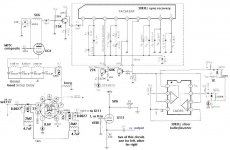
A schematic would be super helpful.
MCAP12 (now free) has good filter design capability, you might want to try that for audio filter design.
I stuck the filter between the 6C4 tube plate, and the plate load resistor 2.7K.The source impedance is thevenin equivalent of rp (plate resistance) in parallel with RL(load resistance). The terminating impedance is whatever you hang on the output of the filter.
A schematic would be super helpful.
.
So I'd think the plate resistance alone would be the source impedance not including the plate load?
And I'd have to have the 38KHz recovery circuit (the PLL chip) connected to the output of this filter (which I didn't do in the schematic yet), so the filter's group delay is normalized out (IOW making the filter group delay not matter).
Attachments
Last edited:
For the third time. Please listen to what you're told here. The 19KHz, 38KHz, and de-emphasis filters go after the MPX. The MPX produces the 38KHz hash, so putting the filter before it is futile. The filter's group delay is therefore immaterial. And driving a device that produces a 38KHz square wave by doubling a 19KHz pilot tone from the output of a filter that removes it is just nonsense.
For the third time. Please listen to what you're told here. The 19KHz, 38KHz, and de-emphasis filters go after the MPX.
Think I forgot to say that this filter is to remove SCA signals. 🙂 A low pass filter set to about 55KHz.
You need a broad notch filter for SCA, not an LPF.
But you can phase comp an LPF, at least in the critical band, with an all pass. Can’t do that as easily with a notch. But it will mess with separation big time unless phase optimized, and even a bit after. It’s not impossible if you have an alignment generator. You do, right?
The SCA filter absolutely must be between the composite input and the 38khz demod, which because of how it works, will create hash that will Intermed with any SCA present, and you’ve got the classic SCA birdies. The IM birdies are upper mid band audio, so you can’t filter them out post demod.
But the filter is a major pain. It needs to be an active just to avoid going insane tuning it up.
This is what’s wrong with the classic switching 38k demod, and why the modern good stuff doesn’t do it that way anymore. Cleaner demods, less hash, less SCA IM, less (or zero) need for the infernal filter.
You can't be flat to 53KHz and get any significant roll off around 67KHz with an LPF unless it is about ninth-order. This problem was solved in the early 1960s, and it doesn't require an LPF or an active filter. Just a cool, a resistor, and a capacitor.
You can't be flat to 53KHz and get any significant roll off around 67KHz with an LPF unless it is about ninth-order. This problem was solved in the early 1960s, and it doesn't require an LPF or an active filter. Just a cool, a resistor, and a capacitor.
cool=coil...but...
Even a second oder Bessel with nominal stop band of -20, 3kHz wide (not really enough, it's less than -10dB at the edges), still throws phase shift into the 25-40kHz range that needs to be compensated for or separation will be compromised. To get the notch to really work right it needs to be higher order, and that just makes it a pain to do with passives.
My point really is, any 67kHz filter at all is a compromise. Its applying one bandaid on top of another. The 1960s solution wasn't really all that good.
If a contemporary demodulator is used, no filter is required because the products that intermod won't be there in the first place. And all performance is better.
I frankly am puzzled by the project in the first place, why would anyone want to use such a primitive design just to utilize a tube? And if tube usage is the goal, why is it the demod? Why not just drop the tubes in the output stage and use a modern stereo demod without all these issues?
But if somebody sees the point, that's fine. IMO, if tube usage is important and performance is important too, the design won't nail both.
Bessel would be the worst possible choice for this. Not enough roll off. I don't know why you even mention it. You can get -40dB easily, and even -60dB with a well designed notch filter. They were doing this stuff in the 1930s.
You've missed the point completely. You can pick your tuning, Bessel, Chebychev, Butterworth, it doesn't matter, you still end up with phase shift in the 38kHz subcarrier band that will scramble your recovered separation unless you deal with it. A phase shift of 45 degrees or so just above 38kHz will blow away somewhere around 6 - 12 dB of separation (frequency dependent of course, with highs collapsing first), just as a L+R to L-R gain mismatch of .5dB will result in only 30dB of separation. Combine gain mismatch and random 38kHz phase shift and you'll have rather poor separation performance.
This is a rather critical matrix circuit. You can't just throw filters anywhere and not pay attention to the resulting phase shift and separation loss. If all you want is 30dB of separation, then I guess it doesn't matter, but we transmit signals with inherent capability of 55dB+, so....if you want random high-blend, then forget any of this and you've got it.
Again, all of these problems have been solved, but not with an early 1960s style demodulator. Hence my lack of clarity on "why".
- Home
- Source & Line
- Analogue Source
- Build a FM stereo decoder using chip and tube