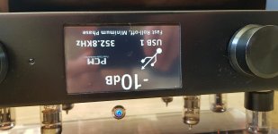
Thank you very much Dim. My display is exactly the same as your first link.
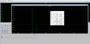
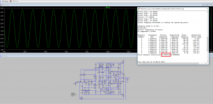
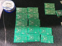
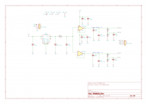
Due to high output current in quadrupler mode of the DAC i deside to use discrete opamps. Here is some picture of the opamps and simulation as a I/V Convertor.
Due to high output current in quadrupler mode of the DAC i deside to use discrete opamps. Here is some picture of the opamps and simulation as a I/V Convertor.
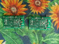
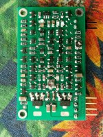
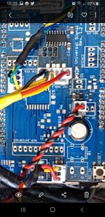
Here are the pics of hand soldering opamps.
The opamp project is developed by my frend!
The opamp project is developed by my frend!
Attachments

If your TFT is this one: 4.3 inch TFT Touchscreen Display for Arduino – SainSmart.com
then its pinout is exactly the same as the 3.2" TFT that I'm talking about here: 3.2″ TFT pinout & connection to Arduino MEGA (or Due) | Dimdim's Blog and here: 3.2″ TFT connection to Arduino Due (UPDATE!!) | Dimdim's Blog
Good job on the PCB. 🙂
Hi Dimdim first of all thank you for all your hard work on making my dac display possible.
I added a display to my dac in 2016 using your buffalo code and your shield.
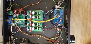
My dac is a diyinhk es9038pro with diyinhk isolated xmos pcbs.
My dac does have use G104 signal that has a pin on my dac pcb that comes direct from pin 26 of es9038pro.
The problem I am having is I get no lock signal but volume control ect work.
If I press the reset button on my shield it all works perfectly giving me the correct sampling rate.
The only part I have got implemented on my shield is the 12c isol1 remote and display.


Hi;
First of all thank you to Dimitris for his help ...
I drew a small PCB to connect LCD from the outputs of Due. It was very successful. I can share eagle file or gerber files who are want...
I asked question to Dimitris for adapt to code for Diyinhk es9028pro board and after i I made simple changes on the code according to the answer.
[/url][/IMG]
[/url][/IMG]
[/url][/IMG]
[/url][/IMG]
[/url][/IMG]
[/url][/IMG]
[/url][/IMG]
[/url][/IMG]
Hi;
First of all thank you to Dimitris for his help ...
I drew a small PCB to connect LCD from the outputs of Due. It was very successful. I can share eagle file or gerber files who are want...
I asked question to Dimitris for adapt to code for Diyinhk es9028pro board and after i I made simple changes on the code according to the answer.
Hi sercan85 what changes do I need to make please
I tried loading your images but my pc and phone are not loading them for some reason.
Last edited:
Hi dear Dave,Hi sercan85 what changes do I need to make please
I tried loading your images but my pc and phone are not loading them for some reason.
We changes;
1.Spdif units d7 d8 input place for my spdif card
2.when i play dsd256 and dsd512 lcd showing dsd64, it is ok now.
3.Hex code for apple remote controller
4. 2nd encorder for menu and input selection
5. autome mute led gpio1 active, and when automute active dac output going 0 ground. ( some registers changes according es9028pro datasheet) bcoz when ı listening dsd on volumio native dsd mode, change music or forwadd music ı here so much crankling sound.. now it is so good and ı dont here crankling sound.... ıf i want to use relay mute on off with gpio1 as a electronic electronics companies but i dont want use signal line a relay...
DIYINHK ES9038pro
Hi I am looking for help with my dac please.
I am using dimdim codes for es9028/9038pro on diyinhk es9038pro pcb.
Problem 1.
I have to reset arduno by power off/on when changing music or it says no lock and stops controlling dac chip.
Problem 2.
I can only get usb input to work optical input does not work.
Problem 3.
When I change tracks or reset I get a small thump through speakers.
My diyinhk does say to change conections on pads if using es9018/es9028 dac chip.
I have not done this as I am using es9038pro dac chip.
My dac chip is connected like this to dimdims shield.
SDA-from 20 pin header to i2c 1 on shield.
SCL from 20 pin header to i2c iso 1 on shield.
3.3v from 20 pin header to i2c iso 1 on shield.
GND from 20 pin header to i2c iso on shield
G4 fron 12 pin to iso on shield.
The only code I have changed is clock to 80hz and code for my remote control.
Attachments


give me your mail address dave...
Thank you so much sercan looking forwards to trying your code.
Your dac looks a really high quality build
Thanks sercan I have loaded onto arduno but rotec encoder has sellector has stopped working.
Volume up/down still works.
Also if I sellect imput 1 on remote it sellects menu not usb 1
I cannot try it properly until I get my es9038pro pcb from diyaudio but just thought I would load code to try it.
I can live with it like this because its still better than before but didnt know if there is something ive missed out.
Dave;
i change dimitris major code for 2. encoder. i said you. and remote control for apple tv...
i change dimitris major code for 2. encoder. i said you. and remote control for apple tv...
Hi thanks I have changed remote code allowing for my remote I've also got 2 encoders but was only using 1 before.
I will try it with 2 encoders.
Its not a big deal as I can still use remote control to sellect usb1 by powering off/on.
I will try it with 2 encoders.
Its not a big deal as I can still use remote control to sellect usb1 by powering off/on.
sercan85,
Nice looking pictures. Hope it would be okay if I ask a few questions 🙂
1. What regulators power AVCC_L and AVCC_R?
2. Wondering what you are using for MCLK source?
3. What DPLL settings are typically used?
4. From the pictures it looks like op amps are AD797?
Thanks,
Mark
Nice looking pictures. Hope it would be okay if I ask a few questions 🙂
1. What regulators power AVCC_L and AVCC_R?
2. Wondering what you are using for MCLK source?
3. What DPLL settings are typically used?
4. From the pictures it looks like op amps are AD797?
Thanks,
Mark
Last edited:
Hi Mark I have got the same psu pcbs they are from diyinhk and have LT3045.
For AVCC?
If so, LDOs of that class are not very good sounding when used for AVCC. Only use such regulators for digital and RF loads myself. Everyone who has tried LT304x or ADM7150 family regulators vs opamp regulators for ES9038Q2M AVCC has always described sound quality as much better with the opamps.
At one point tried to see if AD7150 LDO regs could be made to sound better for AVCC. Found that increasing input voltage from 5v to 7v helped, and also adding 33-ohm, 1/2-watt load resistor from output of regulator to ground helped too. Tried the same LDO AVCC experiment with ES9028PRO and found same results. Then tried using two AD797 opamps as AVCC regulators, one for AVCC_L and one for AVCC_R. That sounded best.
When we are modding Chinese ES9038Q2M dacs I tell people that LT304x can be used as a low-noise voltage reference for a dual opamp AVCC supply. Originally tried LTC6655 as the voltage ref, but LT304x is also very low noise and should work fine.
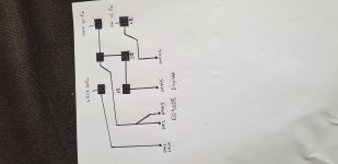
Will attach schematic below of opamp regulator. If opamps are AD797 then can supply enough current for ES9028PRO AVCC, but only for one L/R channel per opamp. They may get warm and possibly benefit from heat sinks.
Regarding the schematic below, lowest distortion is obtained if Vref is adjusted to make I/V opamp outputs rest at zero volts when no music is playing. A pot can be used to find the correct voltage divider values or a formula is available to calculate them. The purpose is to remove the ESS 'hump.' However, it is reported that the hump cannot be removed if using AD797 opamps for I/V and differential summing in the output stage, even if Vref is adjusted. The recommended opamps are OPA1612 or OPA1611. Those are the same opamps now used for ESS eval boards, and for AK4499 dac eval board I/V.
Attachments
Hi Mark my board is different board from diyinhk its the es9038pro board.
It draws a lot more current than the es9028pro so I dont think this op amp psu will be enough if it gets hot with es9028pro.
I am also not using op amps on outputs I am using a tube output stage which I got from lampizator about 8 years ago.
It draws a lot more current than the es9028pro so I dont think this op amp psu will be enough if it gets hot with es9028pro.
I am also not using op amps on outputs I am using a tube output stage which I got from lampizator about 8 years ago.
Hi Mark my board is different board from diyinhk its the es9038pro board.
Yes, ES9038PRO is a more of a problem. Don't have an ideal solution for it. You may find your AVCC LDO is already operating at close to its sweet spot. Data sheet may show that PSRR and or regulation depend somewhat on voltage drop across the regulator and or output current. If it is not currently at the optimum for those things you may find that adjusting them closer to optimum offers some sonic improvement. Thing about AVCC is that it has zero PSRR so it is not unusual for changes to voltage regulator operation to have some audible effect at the dac output.
- Home
- Source & Line
- Digital Line Level
- Buffalo III upgraded with ES9028Pro