So, the loopback measurement was done SE?
Previously presented measurments was done balanced (PP). Whed I disconnect one balaanced output eg OUT- then 3rd harmonic stays and additionally 2nd harmonic shows up
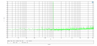
BuffaloII SE (one complementary output) to EMU:
An externally hosted image should be here but it was not working when we last tested it.
Last edited:
You should not be seeing that degree of 3rd harmonic, something is clearly wrong either with the setup or the measurement. It is not easy to obtain good measurements from a PC solution even from the EMU device. The problem is that the ADC itself can introduce some very nasty errors. This will not really be noticed in a loop-back situation. Also simple things like how you run the measurement cable etc can make very large differences.
Since you are using the DAC in an extremely bad setup (voltage out etc) I am not completely surprised. But your measurements are particularly off even compared with what others have posted here and other threads, but most of those people are measuring complete solutions.
We have had the Buf II tested several times with AP. And we easily achieve the results stated in the datasheet with IVY-III. Legato also comes very very close, but it has no global feedback, so THD is very slightly higher.
Last edited:
You should not be seeing that degree of 3rd harmonic, something is clearly wrong either with the setup or the measurement. It is not easy to obtain good measurements from a PC solution even from the EMU device. The problem is that the ADC itself can introduce some very nasty errors. This will not really be noticed in a loop-back situation. Also simple things like how you run the measurement cable etc can make very large differences.
If problem is in EMU's ADC is must be visible on loop test (physical cable from EMU DAC to EMU ADC) but it isn't. Both situations are the same, only different DAC
I use gold plated XRL (CANNON) interconects based on top of the line germany professional microphone cable KLOTZ MY206 soldered with tin and silver.
Since you are using the DAC in an extremely bad setup (voltage out etc) I am not completely surprised. But you measurements are particularly off even compared with what others have posted here and other threads, but most of those people are measuring complete solutions.
Sabre32 DAC in voltage mode should have -108dB THD - its enough for me. I use this setup because of testing tube output stage (tube is voltage driven device).Before I do measure performance of tube stage I need to define source (BuffaloII) and meter (EMU ADC) performance. And I did, and my results are that the EMU DAC with OPAMP output stage has better THD performance that alone BufII (I'm suprised).
I know that datasheet THD is true for sure - I try to figure out what is the reson of my bad results.Maybe I made something wrong or my BufII is lightly broken...
I've just made a test using Jensen JT-11P-1 (1:1) as a simple passive output stage which provide galvanic isolation and BW limiting but THD results are the same..
We have had the Buf II tested several times with AP. And we easily achieve the results stated in the datasheet with IVY-III. Legato also comes very very close, but it has no global feedback, so THD is very slightly higher.
Have you measured BufII in voltage mode (no output stage) with AP? can you post result here?
No, I actually have not measured it like that (no output stage) , because I know the results would be far from ideal. 🙂 Even in voltage mode you would want to do some form of output stage. Direct is never going to be an excellent option.
Last edited:
Ok, got it, but what can I do to stay voltage out (for tubes) and heve better performance?
Anyway I'm wondering in what conditions ESS achieved those -108dB..
Anyway I'm wondering in what conditions ESS achieved those -108dB..

Yeaa..I was there (in OPAMP world) and never come back again...
I definetaly prefer -90dB 3rd harmonic over -120dB from OPAMP output and I think I'm not alone.
Anyway, thanks for you help.
I definetaly prefer -90dB 3rd harmonic over -120dB from OPAMP output and I think I'm not alone.
Anyway, thanks for you help.
Raytech suggests that the noise spectrum will change with (I suppose) quantizer bit-depth? If so, it is very simple to program the chip with different quantize4r bit-depth. (I also use the Buffalo in voltage mode straight to the amp -thus the higher level of interest here)
Basically it just changes the spectra of the noise from the modulators. THD is actually not effected very much, DNR however can be effected to a little greater degree.
Like I said though I only check after an I/V stage. I have not observed what might happen without one.
Dustin actually covered this topic pretty well.
In both THD and SNR the measured change is quite small. Now how it sounds to your ears well thats subjective. The default setting is the one that measures the best. You may want to experiment a bit, but you won't see large swings in any case.
I would be intrigued to see if you find something different.
Last edited:
The default setting is the one that measures the best. You may want to experiment a bit, but you won't see large swings in any case.
Perhaps discrete op-amp's?

Headrott,
I would be very interested in your experience with the tubeizator boards.
OK, I will hopefully get the R-core transformers somethime this coming week and will be able to power everything up. I'll let you know what the results are.
Greg
I have played all the sources listed above on Buffalo II with the DIP switch 4 position "ON". As a matter of fact, I have never set the switch "OFF".I have several doubts for DIP switch settings position 4:
-Position 4 "ON" SPDIF (not I2S?) / PCM support FLAC 24/192?
-DSD 64/2.8224Mbit/s files, have I to change position 4 to "OFF" as per your manual, right?
-How setting for DXD 24BIT/352.8kHz files, setting "OFF" like DSD?
-How to setting WAV 24BIT/96kHz files, setting "OFF" like DSD?
You are not required to set the switch "OFF" even if you play DSD sources. You can get a sound output with the switch "ON" anyhow.
To say exactly, in my case, 2L FLAC 24/192 files were converted into WAV 24/192 files on my PC and 24/192 PCM data was sent via I2S from my SDTrans player. A DXD file does contain not 1 bit stream data of DSD-family but true PCM data. A WAV 24/96 file contains PCM also.
As LeonvB replied, the IIR filter bandwidth can be changed depending on this switch setting. As for "50k" you can look at its frequency response graph on a datasheet. As for "Normal" I have no idea.
According to my understanding, Marek has never described his source for his measurements.BuffaloII to EMU:
What kind of input data did you prepare for your measurement indeed? Can you eliminate a possibility that those harmonics are of source origin?
On the other hand, can you estimate the input impedance of your EMU balanced/single end input respectively?
Ok, here is my setup:
PC->USB-> PCM2704->SPDIF->BuffaloII->XLR->EMU
As you probably know PCM2704 is USB->SPDIF converter made by TI.
Testing software is commonly used RightMark Audio Analyser (RMAA ver 6.2.3) which has dedicated digital data for every test (THD, IMD, DNR, freq resp. etc.).
All test made at 48kHz/16bit (max available sampling rate and bit depth of PCM2704)
I really don't think that this -90dB 3rd harmonic has something to do with source (hardware and software).
Specs of my EMU device declare input impedance of 1M Ohm.
I think if Russ share AP voltage mode no output stage measurments there will be no doubts regarding my equipment and metodology.
All test made at 48kHz/16bit (max available sampling rate and bit depth of PCM2704)
Thank you very much for your prompt reply.
How about your sampling conditions on EMU device and FFT conditions on RMAA?
I'm sorry that I forgot some additional questions in my previous reply.How about your sampling conditions on EMU device and FFT conditions on RMAA?
Did you change any ES9018 register values when you used your Buffalo II board?
Or how did you set up DIP switches on Buffalo II at your measurements?
- Status
- Not open for further replies.
- Home
- More Vendors...
- Twisted Pear
- Buffalo II