Okay, stand corrected, but it would get it going, and final adjustment must be done in its chassis, for correct temperature
Amplidude please give detailed explanation for your post....”final adjustment must be done in its chassis, for correct temperature” ?
Thanks
Well, if you have all boards laying on table and adjust everything to spec, it will behave different when its put into chassis with lid on, heat flow is much different, and it must be taken in account
Looks to me like hschier has a problem. Seems to be 3.242 volts on the output. Does adjusting the offset preset have any effect on this? You don't need the output devices installed to check that all is well as you can see from the manufacturers instructions in post #658. Amplitude is correct about the final setup - must be done with finished amp in enclosure.
Looks to me like hschier has a problem. Seems to be 3.242 volts on the output. Does adjusting the offset preset have any effect on this? You don't need the output devices installed to check that all is well as you can see from the manufacturers instructions in post #658. Amplitude is correct about the final setup - must be done with finished amp in enclosure.
Chalky
Y have a +- 52v rail power. I check v2 and is +-32v.
I am using 556/546 and 560/550 pair.
I turn vr1 but output voltage is -3.2 with no change.
Where do I have to check first ?
Thanks.
Last edited:
Did you get the pinouts right? The devices that you used have different pinouts from the PN100A/200A and 2N5401/5551 specified in the original design. You need to put your devices in "the wrong way round" to that indicated on the pcb. Did you do this? I assume that you made the substitutions in the input stage of the power amp only?
Have you got all three earths connected to 0V? What's the voltage between the bases of Q11 and Q12? Does it vary as you turn VR2? Check all of the component values, location, and orientation again. Are all the necessary components inserted for testing? For some reason you don't have 100% dc feedback setting the output to 0V.
A lot in the sound of the clone depends on the separation capacitors-the input module-the main input. By the way, the second can be excluded with a good setup of the input module.
Have you got all three earths connected to 0V? What's the voltage between the bases of Q11 and Q12? Does it vary as you turn VR2? Check all of the component values, location, and orientation again. Are all the necessary components inserted for testing? For some reason you don't have 100% dc feedback setting the output to 0V.
I connect to ground the point on the corner too and out voltage is 4,57v.
Rail voltage is +-54.5v.
V1- is -32v
V1+ is +32v
Vb q11= +3,2v
Vb q12= -0.1 v
Something not right with the input stage. The bases of Q1 and Q2 should be at 0V ( I assume all of your voltages are measured with respect to 0V? ). What value of R2 are you using? Resolder all of your soldered joints around the input stage, especially R1,R2,R3. Did you check the components before you soldered them into the pcb?
Chalki. Thanks for the help. This is my first diy amp building
The actual situation:
Amp board is without 21193-21194.
There are 1 ground cable pgnd beside -v1 in amp board and two cables pgnd con2 and signd con3 from power supply ground.
Q1q3 are bc550c Q2Q4 bc560c
Q5 bc546b Q6 bc556b
Q18 mje15035 Q17 mj15034
R1= 10
R2 = 1,2k
Vr15 31.6v voltage drop between R15
Vr17-26v
Vr11 20v ( r11 smell like burn)
Vr14 5v
Vbq1=Vbq2=Vbq3=Vbq4= -25.8v
Vbq11 = -2.7
Vbq12 = -25v
Vbq15= -31.5
Vbq16= 34.5
All measure with respect to 0v
Last edited:
Your amp might be oscillating. Try increasing C12/13 to 150p. You could also try putting Q5/6 back to the original 2N5401/5551. Again check that all the right components are in the right place and in the correct orientation. In the past I've done this check three or four times and everything looked ok, but on the fifth check I found a diode, zener, or other semiconductor inserted the wrong way round. Check twice on two consecutive days and power up once. My experience is that most problems are caused by stupid mistakes.
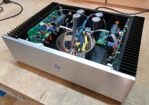
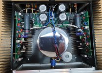
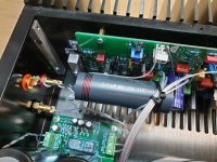
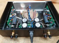
Bryston 3B SST clone - in final case
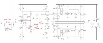
Here is my promised update of this build😀
In the final case with proper wiring - AC/signal/DC power separated as much as possible.
- Running at +/- 49V, 300mA bias / channel
- without input board - My muses02 opamp preamp can easily drive this amp
- all transistors and symmetrical resistors matched
- PN100A/PN200A input stage
- 300VA transformer
- 4x 20 000uF filter caps
- Input caps 2,7uF Jantzen Alumen Z-Cap
- Attached is a cirquit diagram of my mods
Cheers
Paul
Attachments

Last edited:
Wow....congratulations, bias 300ma ?Here is my promised update of this build😀
In the final case with proper wiring - AC/signal/DC power separated as much as possible.
- Running at +/- 49V, 300mA bias / channel
- without input board - My muses02 opamp preamp can easily drive this amp
- all transistors and symmetrical resistors matched
- PN100A/PN200A input stage
- 300VA transformer
- 4x 20 000uF filter caps
- Input caps 2,7uF Jantzen Alumen Z-Cap
- Attached is a cirquit diagram of my mods
Cheers
Paul
Yba p1000
hello how is yba p1000
Any of you guys seen/tried these amplifiers? Designed by the same guy who did the Bryston 4B SST boards. They seem to be a more conventional design so I've bought a couple to see what they're like.
Pair of 400W+400W Stereo Power Amplifier PCB Board based on YBA P100 Amp C 2.0 | eBay
hello how is yba p1000
Hi....all can anyone can send me the link for pcb terminal blocks in power supply pcb .?I tried few but pin distance are different.
Thanks
Thanks
- Home
- Amplifiers
- Solid State
- Bryston 4B SST clone