inputs and outputs
Hi friends, yesterday I bought some Malone PW-1222 speakers of 300Watt RMS, and in your connections has speakon input, speakon outuput, jack 6.35 two, and threaded terminals, what type of cable can I use? XLR and RCA board connections are audio inputs or speaker outputs? what are the audio inputs and outputs for speakers? so to be sure what kind of cables I should buy to connect to the malone, thanks
Hi friends, yesterday I bought some Malone PW-1222 speakers of 300Watt RMS, and in your connections has speakon input, speakon outuput, jack 6.35 two, and threaded terminals, what type of cable can I use? XLR and RCA board connections are audio inputs or speaker outputs? what are the audio inputs and outputs for speakers? so to be sure what kind of cables I should buy to connect to the malone, thanks
Attachments
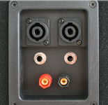
These are all highlevel amplified inputs. Run a connection from the outputs of your amp to one of these of your liking. I'd prefer speakon because it's the most reliable of the three.
But if I were you I'd bring the speakers back to where they belong. Maybe the junkyard. They're not worth the material they're made of. Horrible stuff.
But if I were you I'd bring the speakers back to where they belong. Maybe the junkyard. They're not worth the material they're made of. Horrible stuff.
A diy project like the 28b isn't a cheap endeavor, and it should perform very well, it deserves good speakers.
These are all highlevel amplified inputs. Run a connection from the outputs of your amp to one of these of your liking. I'd prefer speakon because it's the most reliable of the three.
But if I were you I'd bring the speakers back to where they belong. Maybe the junkyard. They're not worth the material they're made of. Horrible stuff.[/QUO
XLR is input or output?
I don't see any XLR there. The type is following a standard. Every in and every out is always the same. Google might help you...
In case of rca it depends of for what it's used for. Give us more information. Nobody understands what you want...
In case of rca it depends of for what it's used for. Give us more information. Nobody understands what you want...
I don't see any XLR there. The type is following a standard. Every in and every out is always the same. Google might help you...
In case of rca it depends of for what it's used for. Give us more information. Nobody understands what you want...
In my post is PDF of schematic is CON1 and RCAis CON2
They're both inputs....
Hi friend, and outputs to speakers what which type are?
Hi amplitude and friends, In debbugging instructions said:
"Do not install the power tube before power-on and the transformer is connected in series. 60‐100W Incandescent bulbs, especially all SGND and PGND on the board"
What does it means? the bulbs are in primary o secundary of trans?especially all SGND and PGND on the board?
The interconections diagrams of psu input and amp PSB are really poor. Do you have a better one?
Thanks
Hi amplitude and friends, In debbugging instructions said:
"Do not install the power tube before power-on and the transformer is connected in series. 60‐100W Incandescent bulbs, especially all SGND and PGND on the board"
What does it means? the bulbs are in primary o secundary of trans?especially all SGND and PGND on the board?
The interconections diagrams of psu input and amp PSB are really poor. Do you have a better one?
Thanks
I think it connects in the primary
Hi.
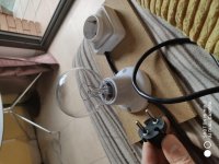
Jose is correct, the bulb goes in series on trafo primary side, see attached pic.
And also it says you must try powerup without power transistors installed.
Good luck, check everything thoroughly first, bulb will light up briefly and then dim, that's normal, capacitor charging.
Jose is correct, the bulb goes in series on trafo primary side, see attached pic.
And also it says you must try powerup without power transistors installed.
Good luck, check everything thoroughly first, bulb will light up briefly and then dim, that's normal, capacitor charging.
Attachments

Hi.
Jose is correct, the bulb goes in series on trafo primary side, see attached pic.
And also it says you must try powerup without power transistors installed.
Good luck, check everything thoroughly first, bulb will light up briefly and then dim, that's normal, capacitor charging.
Attachments
bobina if you look back to post #369 you'll see I detail all of the changes I made to the parts you mentioned. I made the changes because the PN100A/PN200A are obsolete. I know, so are the BC560C but I have a large stash of them, as do many other people. If you want current production devices then use the KSC1845/KSA992 pair ( with a bit of lead dressing ). I changed the resistor values so that the quiescent current of the VAS transistors Q5/Q6 was cut from 12mA to 6mA. At the original current Q5/Q6 were dissipating 400mW and ran pretty hot - now they run cool. To cut the loading on Q5/Q6 now that the standing current was reduced I used output devices with potentially 4x the hfe of the MJE172/MJE182. I've redrawn the schematic with my revised parts values and attached it to this post.
Thank you for the changes in the scheme. It is steady, temperature is normal. My opinion is not enough slew rate, I wanted more.
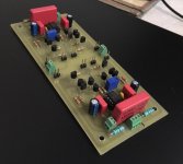
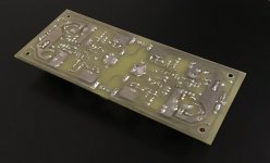
I use a circuit very similar to that for both a headphone amplifier and a buffer amplifier. Very easy to set dc quiescent conditions and pretty low distortion. I'll try and dig out a photo of a populated pcb.
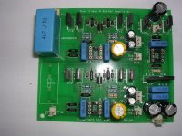
Here's my version. Components down the rhs are a rail splitter and capacitance multipliers. Designed to be run from a single +24V supply. I have used constant current diodes to bias the diamond buffers and two pairs of output devices in parallel on each channel. This is obviously my pcb for experimenting with.
Attachments
Indeed, lots of possible variations on this theme. You can also use high voltage opamps like the opa445, or bootstrap the opamp power supply, to get higher overload margin. I like the constant current arrangement in your first schematic, it ensures that each half of the diamond buffer gets exactly the same bias current.
- Home
- Amplifiers
- Solid State
- Bryston 4B SST clone