It certainly is an AB design. I would go ahead and buy 6 mosfets and use them as they are.
This link will drop you into the middle of the thread and also to Shawn's link with all the details http://www.diyaudio.com/forums/showthread.php?postid=945573#post945573
Q
This link will drop you into the middle of the thread and also to Shawn's link with all the details http://www.diyaudio.com/forums/showthread.php?postid=945573#post945573
Q
quasi said:It certainly is an AB design. I would go ahead and buy 6 mosfets and use them as they are.
This link will drop you into the middle of the thread and also to Shawn's link with all the details http://www.diyaudio.com/forums/showthread.php?postid=945573#post945573
Q
so thats original working schematics?
http://www.raindogindustrialarts.com/Images/NCHAN MOS PROJECT 06-05-06.pdf
medogrizli said:
so thats original working schematics?
http://www.raindogindustrialarts.com/Images/NCHAN MOS PROJECT 06-05-06.pdf
That is the latest and best working schematic. It is the only version you should use.
Q
quasi said:
That is the latest and best working schematic. It is the only version you should use.
Q
Ok thanks: it seems great :
I see the pdf: it seems the power supply is not limited to +/-70V it can work at higher rates 😀
So what are the characteristic of the amplifier input voltage THD etc ?
So how did the the development proseeded: did you use computer proframs for analyzing and calculation or you did all manually 😀
I have answered your question here;
http://www.diyaudio.com/forums/showthread.php?postid=1037645#post1037645
Cheers
Q
http://www.diyaudio.com/forums/showthread.php?postid=1037645#post1037645
Cheers
Q
quasi said:I have answered your question here;
http://www.diyaudio.com/forums/showthread.php?postid=1037645#post1037645
Cheers
Q
ok thanks: we can continue to duscuss there cause there is the right topic for mosfet type
😀
Hi Med,
and you still need to take account of the losses from the regulator monitoring points (both 0V and +ve/-ve) through the connecting cables and fuses through the active devices, through the emitter/source resistors, through the Thiel network, through the output cables and finally at the output terminals.
The total voltage lost can be anywhere betewen 2Volts and 15Volts plus the variations coming out from the regulated supply.
This is rubbish.No if I USE SMPS THAT always ADJUSTs voltage CONCERNED to current : it alwas gives THE SAME VOTAGE no matter what current
and you still need to take account of the losses from the regulator monitoring points (both 0V and +ve/-ve) through the connecting cables and fuses through the active devices, through the emitter/source resistors, through the Thiel network, through the output cables and finally at the output terminals.
The total voltage lost can be anywhere betewen 2Volts and 15Volts plus the variations coming out from the regulated supply.
AndrewT said:Hi Med, This is rubbish.
and you still need to take account of the losses from the regulator monitoring points (both 0V and +ve/-ve) through the connecting cables and fuses through the active devices, through the emitter/source resistors, through the Thiel network, through the output cables and finally at the output terminals.
The total voltage lost can be anywhere betewen 2Volts and 15Volts plus the variations coming out from the regulated supply.
Yes thats ok
but this is not the same when using clasical 50hz transformer : The volatage drops when current goes up
There is for sure difference
bigpanda said:Hi Quasi,
would it be OK to use MJ15003 or MJ21193 for BJT version? I had a handful of them.
I will be using MJ15003 in the prototype.
Cheers
Q
Q need big drink after today. DIY is a full time job! 😉 I enjoy reading the correspondence very much.
Cheers,
Shawn.
Cheers,
Shawn.
Sonics - Mosfet vs Bipolar version
I gather that none around here have made both the Mosfet version and the Bipolar version of Quasi's amp, but any guesses on which would be superior sonically?
Depending on the feedback, I wish to put two channels together in the next couple of days to replace Holton's N-channel amps; this means that I have everything already assembled and only the amp boards are going to be replaced.
I'd really appreciate any feedback. Thanks.
Mosfet vs Bipolar version
I have built the quasi mosfet amp with 10 mosfets per channel. I think it sounds fantastic and many others will agree. The bipolar is still on his bench so even Q's opinion is pending but how can a father choose between his two children? I guess you must be right, no one has yet built both? You could be the first if you are fast. 😉
Cheers,
Shawn.
Samuel Jayaraj said:I gather that none around here have made both the Mosfet version and the Bipolar version of Quasi's amp, but any guesses on which would be superior sonically?...I'd really appreciate any feedback. Thanks.
I have built the quasi mosfet amp with 10 mosfets per channel. I think it sounds fantastic and many others will agree. The bipolar is still on his bench so even Q's opinion is pending but how can a father choose between his two children? I guess you must be right, no one has yet built both? You could be the first if you are fast. 😉
Cheers,
Shawn.
Quasi in Sydney
Hi fellow Aussies, I'm in Sydney on Monday and Tuesday night (20/11/06 - 21/11/06). If any one wants to catch up for coffee and a yarn email me a contact number. I'm staying in Chatswood.
Cheers
Q
Hi fellow Aussies, I'm in Sydney on Monday and Tuesday night (20/11/06 - 21/11/06). If any one wants to catch up for coffee and a yarn email me a contact number. I'm staying in Chatswood.
Cheers
Q
Prototype almost finished
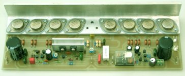
Here's a photo of the almost finished prototype. It's missing the output drivers and the output coil. I revised the layout to suit the heatsink mounting bracket I used and once tested I will post the layout for anyone who is interested.
Cheers
Q
Here's a photo of the almost finished prototype. It's missing the output drivers and the output coil. I revised the layout to suit the heatsink mounting bracket I used and once tested I will post the layout for anyone who is interested.
Cheers
Q
Attachments
Hi Quasi,
That looks professional! Nice work!
It seems that you using Sprint Layout for PCB design. Am I right?
I'm using the 4.0 version, and I'm really pleased with the software. Cheap, but really reliable and practicable. For home usage it's perfect.
Regards,
That looks professional! Nice work!
It seems that you using Sprint Layout for PCB design. Am I right?
I'm using the 4.0 version, and I'm really pleased with the software. Cheap, but really reliable and practicable. For home usage it's perfect.
Regards,
Thanks Edl, yes I use sprint. As you say it's very easy to use (although I had to draw new TO3 devices at an angle). I also like using the fill command to save on etchant.
Merry Christmas to you and your family.
Cheers
Q
Merry Christmas to you and your family.
Cheers
Q
Merry xmas Quasi,
I had a question that I like to ask about the pcb design. At the lower left corner there is a 0.1uf. the lower side of which goes to the ground. Instead of going to the closest ground that the 300uf had, it had to go all the way back to the middle parallel with the 300uf ground. What would be the significance of this? Hope that is not a very stupid question.
Similiar with the -ve rail.
Hi Bigpanda
On the positive rail there are two 0.1uf capacitors. The first one is in parallel with the electrolytic and this one is connected straight across it. These capacitors filter the positive rail after the fuse.
The other 0.1uf is connected before the fuse and provides some filtering to the positive track feeding the first and second stages. This goes back to central ground to avoid the heavy current flows associated with the output stage.
The negative rail is the same. The 0.1uf in the middle of the board filters the negative rail feeding the constant current source. This is also before the fuse and is returned via a seperate track to ground to avoid the heavy currents on the other earth track.
I hope the above makes sense. I have attached the revised layout to show how the different tracks run.
Cheers & happy Christmas
Q
Attachments
- Status
- Not open for further replies.
- Home
- Amplifiers
- Solid State
- Brother of Quasi