Greetings all!
I'm in the process of building a pair of these amps. I have several 6c4c=6B4G and several 6a5g tubes. I'd like to be able to use both. The 6c4c are directly heated cathodes and the 6a5g are indirectly heated.Thought maybe i could make it switchable.
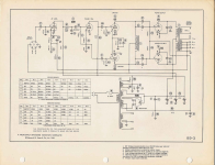
I have seen two different schematics of this amp. I'm a little confused by this circuit. Seems the full rectified voltage appears across C1 with less appearing across C2 and the difference being across R17?
If there is a simple way to set this amp up to use both those tubes? I also read r20 r21 and c6 was mentioned somewhere in the past as significant part of the circuit, yet in the circuit redraw it is omitted. I'm not clear on this.
I have done the metal work and installed tube sockets and transformer layout. I am getting ready to do circuit layout and was looking for some help. hopefully some can shed some light on this.
Edit: not both tube varieties at once,
I'm in the process of building a pair of these amps. I have several 6c4c=6B4G and several 6a5g tubes. I'd like to be able to use both. The 6c4c are directly heated cathodes and the 6a5g are indirectly heated.Thought maybe i could make it switchable.
I have seen two different schematics of this amp. I'm a little confused by this circuit. Seems the full rectified voltage appears across C1 with less appearing across C2 and the difference being across R17?
If there is a simple way to set this amp up to use both those tubes? I also read r20 r21 and c6 was mentioned somewhere in the past as significant part of the circuit, yet in the circuit redraw it is omitted. I'm not clear on this.
I have done the metal work and installed tube sockets and transformer layout. I am getting ready to do circuit layout and was looking for some help. hopefully some can shed some light on this.
Edit: not both tube varieties at once,
Attachments
Last edited:
It is using R17 to make the negative bias voltage for the output tubes , so you don't need a separate winding for this . And of course in 50's extra diodes for rectification were expensive .
I don't think you can use both tubes in the same circuit as 6a5g has the cathode connected to a middle tap of the filament , that direct heated tubes don't have
I don't think you can use both tubes in the same circuit as 6a5g has the cathode connected to a middle tap of the filament , that direct heated tubes don't have
Last edited:
All the B+ current passes through R17. The voltage drop across R17 is needed, it is the negative bias supply voltage for the 2A3 grids.
R20, R21, and C6 are the elevation voltage for the filament of the phase inverter tube; because its cathode voltage is far above the ground voltage.
It saves the filament to cathode insulation of the phase inverter tube.
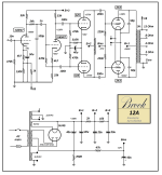
The first schematic does not have any connection to ground that will return the 2A3 filament DC current, H and H. The filaments are floating, there will be no plate current. Needs to be fixed.
The second schematic shows the 2.5V filament winding, X and X, with a center tap to ground. It is the DC return for the 2A3 tubes.
The output tubes have to be Very well matched, whether 2A3, 6C4C, 6B4G, or 6A5G. That is because they do not have individual bias voltages.
The bias circuit is simple, but only because they used Very well matched output tubes.
Otherwise, you have to provide individual bias circuits for each tube; even if you match the DC current, the signal currents might not be matched.
The output transformer Hates Un-balanced DC plate currents (early lamination Saturation).
What output transformer, and what push pull driver choke will you use?
They need to match the original parts, or you may have to revise all the frequency determining poles to get it to work, instead of oscillating.
The circuit signal path has 1 RC, then a pair of RC, then another pair of RC coupling.
It also has 1 push pull choke on the drivers, and the output transformer.
That is 5 low frequency poles; more even than a Williamson circuit.
I hope all those poles are at different frequencies; otherwise you will have a Power Oscillator, instead of a Power Amplifier.
Considering the possible errors in the schematic(s), and the circuit topology, I think you should . . . Trust, but Verify all the details.
There may be lots of other things that I did not spot, they might be a problem too.
Perhaps you should make it all work with 2A3s before you try other tubes.
I do not want to keep you from trying to duplicate that circuit; but you may need some others who have actually built that circuit, and made it work even if the driver choke and output transformer are not original.
R20, R21, and C6 are the elevation voltage for the filament of the phase inverter tube; because its cathode voltage is far above the ground voltage.
It saves the filament to cathode insulation of the phase inverter tube.
The first schematic does not have any connection to ground that will return the 2A3 filament DC current, H and H. The filaments are floating, there will be no plate current. Needs to be fixed.
The second schematic shows the 2.5V filament winding, X and X, with a center tap to ground. It is the DC return for the 2A3 tubes.
The output tubes have to be Very well matched, whether 2A3, 6C4C, 6B4G, or 6A5G. That is because they do not have individual bias voltages.
The bias circuit is simple, but only because they used Very well matched output tubes.
Otherwise, you have to provide individual bias circuits for each tube; even if you match the DC current, the signal currents might not be matched.
The output transformer Hates Un-balanced DC plate currents (early lamination Saturation).
What output transformer, and what push pull driver choke will you use?
They need to match the original parts, or you may have to revise all the frequency determining poles to get it to work, instead of oscillating.
The circuit signal path has 1 RC, then a pair of RC, then another pair of RC coupling.
It also has 1 push pull choke on the drivers, and the output transformer.
That is 5 low frequency poles; more even than a Williamson circuit.
I hope all those poles are at different frequencies; otherwise you will have a Power Oscillator, instead of a Power Amplifier.
Considering the possible errors in the schematic(s), and the circuit topology, I think you should . . . Trust, but Verify all the details.
There may be lots of other things that I did not spot, they might be a problem too.
Perhaps you should make it all work with 2A3s before you try other tubes.
I do not want to keep you from trying to duplicate that circuit; but you may need some others who have actually built that circuit, and made it work even if the driver choke and output transformer are not original.
You can interchange 6B4G and 6A5G. 6A5G's will bias off the filaments the same as 6B4G, or you can use the sleeve output at pin 8.
http://vinylsavor.blogspot.com/2019/12/tube-of-month-6a5.html
http://vinylsavor.blogspot.com/2019/12/tube-of-month-6a5.html
Thanks for the replies fellas. Ok grover thanks i'll check out your link. This is interesting.
@ 6a3summer, are you suggesting that a separate filament transformer and a regulated bias supply with seperate bias pots might be better to use? If an auxiliary PT to generate bias voltage was used, I guess i would ground the cathodes or add the Rk if I want the same feel as the original circuit.? The bias supply would have excess voltage for the bias regulator to work properly and for good control over the tube idle current I assume. It seems its getting quite a bit more complicated to get around the tube matching with my little stash of 6c4c and 6a5g's.
@ 6a3summer, are you suggesting that a separate filament transformer and a regulated bias supply with seperate bias pots might be better to use? If an auxiliary PT to generate bias voltage was used, I guess i would ground the cathodes or add the Rk if I want the same feel as the original circuit.? The bias supply would have excess voltage for the bias regulator to work properly and for good control over the tube idle current I assume. It seems its getting quite a bit more complicated to get around the tube matching with my little stash of 6c4c and 6a5g's.
swingarm63,
Yes. You got my point.
If you try and build an original old circuit, you will have to have identical parts, or re-design the circuit.
Part of the original parts includes: very well matched 2A3 tubes.
Of course, changing tubes to 6C4C or 6A5G, you will need very well matched tubes.
. . . But there are other solutions that do not have to Very well matched tubes, just well matched tubes:
1. Self Bias . . . It is not simple to use Self Bias for 2 or more DHT tubes, such as Parallel Single Ended, or Push Pull.
But yes, for DHT, you will need individual filament windings. And the self bias resistor looses quite a bit of B+,
but on your amplifier circuit, you just make up for that by shorting across the original 700 Ohm resistor. Do not forget to use individual bypass caps across the individual self bias resistors.
Or
2. Individual fixed adjustable bias . . . the fact is that the voltage drop across the 700 Ohm resistor can run separate bias potentiometers. Change the resistor to 750 or 800 Ohms, and you will have extra range on the added individual 10k pots.
Yes, you will have a little less B+ for the output tubes if you change 700 Ohms to 750 Ohms or 800 Ohms.
Or, use the original 700 Ohms, and set the stronger / highest conducting tube 10k pot to max current setting, and the 'less conducting tube's 10 pot to less bias voltage until its current matches the stronger tube.
Decide on the tradeoffs of 1. and 2. above, and move forward with your re-design.
Have fun designing, building, and listening.
Last edited:

Ok if i go with solution 2 what might the bias circuit look like? Do you have a circuit in mind?
I have used separate bias pots for each tube on a guitar amp before. It worked well but was not simple.
I have used separate bias pots for each tube on a guitar amp before. It worked well but was not simple.
Last edited:
OK.
What do you think about:
Changing R17 from 700 Ohms to 750 Ohms
Changing R16 from 47k Ohms to 1k Ohms
Changing C3 from 47uF to 1000uF (be careful of the polarity, the positive end goes to ground)
Then make two individual adjustable bias circuits, one for each 2A3:
20k resistor, one end to ground, the other end to the bottom of a 5k Potentiometer, the top of the 5k potentiometer to the junction of the 1k resistor and the negative terminal of the 1000uF capacitor.
Remove the connections of the two 2A3s 220k grid resistors that each went to the original 2A3 bias circuit. They will now go to the individual bias pot wipers.
Connect the now 'freed' ends of the individual 220k grid resistors, to the bias potentiometer wiper.
Duplicate this for the other 2A3.
Draw that circuit up, and Post it in this Thread, so I can see if you got it right.
Caution: when first powering the amplifier on, start with the bias wiper turned to the end of the potentiometer that is connected to the junction of the 1k resistor and the negative end of the 1000uF cap.
I would suggest you just build the Brook as is. It's a back-bias design, nothing wrong with that, and it's a classic. If you change the bias arrangement you're going to need to fuss with the B+ on the 6B4G's and your power supply will be a mess. It's very cleverly designed to work exactly as is. It's push-pull so unless the output tubes are very poorly matched the filament noise should cancel.
R20, R21 and C6 are there to raise the filament supply of the input tubes a certain voltage above ground, to avoid the heater-cathode limitations of those tubes. They are necessary and should not be omitted.
R20, R21 and C6 are there to raise the filament supply of the input tubes a certain voltage above ground, to avoid the heater-cathode limitations of those tubes. They are necessary and should not be omitted.
grovergardner,
A very clever and very good design, Yes!
It is designed to work with Very Well Matched 2A3s.
Otherwise, it will not perform as it was designed.
And, go and get those original push pull chokes and output transformers too.
Otherwise, it will not perform as it was designed.
Your Mileage May Vary
Just my opinion.
There's no difference between 2A3s and 6B4Gs, except for the filament voltage. Provided the tubes are pretty well-matched there shouldn't be a problem. The OP will never know how the amp sounds if he changes it before he builds it!
grovergardner,
Agreed. Build the 2A3 version first (have to use 2.5V on the filaments).
Then, with the negative feedback "as is" and different push pull chokes and output transformers,
get it on the bench and make sure it is stable with various loads.
Step by step. All things decent and in order.
Now it is time to listen.
2A3 4 pin 2.5V
6A3 4 pin 6.3V
6B4G Octal . . . Different
Then put in 6.3V filament supplies, and use 6.3V tubes.
I'm using a pair of utc mqm-300's for the chokes and vintage hammond 1715 output transformers. I saw someone used the utc's elsewhere with success and found a pair on ebay for a reasonable price. I have a pair of hammond 274bx for power.
I do not want to build this around 2a3 tubes at this time. I scored several 6a5g months ago with some old consoles and a few boxes of tubes. I did'nt even know what 6a5g tubes were lol. I also have 4 6c4c nos tubes i bought years ago. There may be better circuits to build using the 6a5g/6c4c tubes. I just thought it was doable for this circuit so i went ahead and have started.
Last edited:
From your link
"The 6A5 has an 8 pin Octal base. The pinout is shown on the left. It was derived from the 6B4 which is an Octal base version of the 6A3. The 6A3 is a 6.3V filament version of the 2A3. With a 6.3V directly heated filament the 6A3 and 6B4 are prone to hum when heated from AC, while the 2A3 with only 2.5V can be easily operated with minimal hum. This led to the development of an indirectly heated version. The 6A5 is basically a 6B4 with cathode sleeves on the filament. The cathodes are internally connected to the center tap of the filament and to pin 8. This pinout is identical to that of the 6B4 except for the additional cathode connection. Since the cathode is internally connected to the center tap and since the heater current is the same as the 6B4 filament current, the 6A5 can be used in circuits designed for the 6B4 without any changes. Obviously a good idea, but the 6A5 does not seem to have been widely adopted as the tube is rarely seen."
Interesting, It seems I could plan for the bias mod if needed. I like to build on eyelet boards.
Last edited:
This has been very helpful, thanks! I'm tempted to mess with the bias circuit, but will try building as designed first and see how it goes. I should also mention, I chose to use a 6sn7 for the PI. I just didn't have the room for 2 tubes in my chassis.
Last edited:
Ha! I just came across this on ebay!
1pc Dual 6J5G 6C5G VT-94 L63 CV1932 VR67 VT154 TO 6SN7GT CV181 B65 tube adapter
1pc Dual 6J5G 6C5G VT-94 L63 CV1932 VR67 VT154 TO 6SN7GT CV181 B65 tube adapter
Yes, I have those, they work very well. The point of using 6J5s was to allow for better matching of the driver tubes, I think. But a well-matched 6SN7 should work just as well.
- Home
- Amplifiers
- Tubes / Valves
- Brook 12a using 6C4C and 6A5G questions.