Yeah, I don't have any 6J5s but i do have lots of 6SN7s. I think I'll pick up a pair of these though.
Last edited by a moderator:
Just don't be too disappointed when the amp is very difficult to stabilize. My building partner (itishifi.com) built a pair a few years ago, because they were Paul Klipsch's recommended amps at one time, using brand H iron said to be wound to original specs, yada yada, and he wanted to see what the buzz was about. We futzed with various compensation schemes and reduced feedback, etc. trying for a stable compromise, but he eventually tore both chassis apart for the parts in disgust.
Very complicated amp designs from the 1950s, 1960s are just not a good choice for a modern DIYer. They depend critically on very particular transformer characteristics and impossible levels of valve matching, usually for reasons (like the high cost of capacitors) that just don't apply anymore. Nostalgia is fine, but parasitic oscillations are not fun. Choose fun.
All good fortune,
Chris

Ok thanks Chris! I guess the worst case is, I abandon the circuit and use the amps with a different circuit. I'm going to persist for a bit 🙂
Last edited:
To be clear, "brand H" is not Hammond, but a well known custom winder. My concerns are with any complex amplifier with long loop feedback. Stretching this loop feedback over several stages and two(!) inductors is just madness. Just say no.
A push-pull 2A3 amplifier used in an appropriate system doesn't need long loop feedback. It's potentially cleaner than any likely loudspeakers it's driving, within its dynamic range. A modern use of the same inductor set might move the bifilar choke to the cathodes of a push-pull cathode follower driving the 2A3s, with individual cathode bias, center tap to signal ground. Good for grid leakage current, good for driving Miller C, good for capacitive modulation of Miller C, much less critical to include into stability decisions, much better overload recovery behavior, much less effect on open loop phase response. Und so weiter. The loss of the long loop feedback is both a blessing and a curse, but it can be more of a blessing in this specific case.
You're doubtless determined to joust at this windmill, but maybe this might be a fall-back position, or at least a future exploration.
All good fortune,
Chris
(I'll try this post again again and not say anything about the the federal reserve LOL)
The Brook 12a is not my enemy 🙂 If it kicks my ***, then so be it. I'll be sure to report back and let you know how it went! Cheers!
The Brook 12a is not my enemy 🙂 If it kicks my ***, then so be it. I'll be sure to report back and let you know how it went! Cheers!
OK.
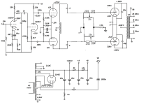
What do you think about:
Changing R17 from 700 Ohms to 750 Ohms
Changing R16 from 47k Ohms to 1k Ohms
Changing C3 from 47uF to 1000uF (be careful of the polarity, the positive end goes to ground)
Then make two individual adjustable bias circuits, one for each 2A3:
20k resistor, one end to ground, the other end to the bottom of a 5k Potentiometer, the top of the 5k potentiometer to the junction of the 1k resistor and the negative terminal of the 1000uF capacitor.
Remove the connections of the two 2A3s 220k grid resistors that each went to the original 2A3 bias circuit. They will now go to the individual bias pot wipers.
Connect the now 'freed' ends of the individual 220k grid resistors, to the bias potentiometer wiper.
Duplicate this for the other 2A3.
Draw that circuit up, and Post it in this Thread, so I can see if you got it right.
There is a bit of cathode-bias and fixed-biasing in the 12a, yes? Seems it would be best to make sure it works and then measure the DC voltage on the divider and on Rk? It seems If you reduce the tube current, the supply voltage might rise since it appears to be shared between R17 and the rest of the circuit, no? There seems to be a reaction that may be hard to overcome without adding a seperate bias supply and allowing the full voltage from the plate winding to act across the circuit. Seems it may mean adding a voltage regulator or changing other values in the schematic.Not so simple I guess.
Was just reading this about back biasing
What is back biasing
https://www.aikenamps.com/index.php/what-is-back-biasing
Last edited:
The 12A is not fixed biased.
It uses self bias; but admittedly, the self bias voltage is dependent on the currents of all the tubes.
Do not worry, the majority of the current in the 700 Ohm resistor is from the two 2A3 tubes (The two 2A3 currents are the Dominant factor of the bias voltage that is applied to the 2A3 tubes).
It does not use Individual self bias for each 2A3 tube.
It is time to either build the amplifier with 2A3 tubes, and see if you can make it stable; or decide what else to do.
I expect the stability issues to be essentially the same for 2A3, 6A3, 6B4G, 6C4C, and 6A5G.
The different plate impedance, rp, of those various tubes will perhaps be the largest factor.
Last edited:
It sits half completed on my shelf LOL! I'm going to get to it but I have been very busy. Also I tend to get too many projects going at once.
I'm building a 26 preamp and this amp as time permits.
https://rh-amps.blogspot.com/2014/04/rh-tta-tube-tester-amplifier.html
I'm building a 26 preamp and this amp as time permits.
https://rh-amps.blogspot.com/2014/04/rh-tta-tube-tester-amplifier.html
Totally understandable and relatable. I was just wondering how it sounded, so I'll have to wait for your review. Good luck with your projects.
Indeed! However, Thanks for asking about it MissionX . It is a tough build to do right but I will look at it again soon! Here is what it looks like on the shelf. I still need to put Power transformers in but recently found a matching vintage hammond 700vct transformer to one on my shelf on ebay. Very reasonably priced here in Canada with free shipping so I bought it. I'm a little intimidated by this amp but will give it go in a few months. I like using fiberglass board that I get from Aliexpress for very reasonable prices. I build guitar amps too and use that board for them. However I find terminal strips too expensive for what they are these days and eyelets are nice and are so easy to change values/parts. Yes e_fortier my wife says all projects must stay in the basement or workshop! no half built equipment allowed on the main floor LOL
Edit: Note in the pic , I already stole a Solen cap from this amp for another project! 🙂
Cheers!
Edit: Note in the pic , I already stole a Solen cap from this amp for another project! 🙂
Cheers!
Attachments
![IMG_3116[1].png](/community/data/attachments/1177/1177629-f44bc67cccc711a3b7b40d1819d0fb23.jpg?hash=9EvGfMzHEa)
![IMG_3117[1].png](/community/data/attachments/1177/1177631-5773b3ca44e620beaa736277c69215dd.jpg?hash=V3OzykTmIL)
Last edited:
Yes. Getting it right seems a chore. I've been told the schematics aren't correct. Yours look nice so far.
Thanks MissionX ! Just a hack, trying to get the job done!! I had some scrap stainless steel and made the chassis. Stainless steel is not fun to work with but i had it, so why not.
Yeah it seems the schematics are not complete . I have studied this interesting schematic and will slowly get this done! (I hope).
I'm not an engineer , and have been told a few times that this amp is not a mix of fixed and cathode bias, but it appears that way to me!
It seem like r17 should be drawn with the ground at it's top, allowing you to see how the bottom end appears negative. The full rectified voltage
is seen across c1 with less appearing at c2 and the difference being across r17.
Not to hijack my own thread but here is a pic of the project that stole me away from the brooks for a bit ( still have a ways to go on this preamp too. The design is by 26 DHT Pre-amplifier (Gen3) by Bartola Valves and the other amp I'm working on is the RH-tta but I will not get carried away with pictures. LOL
Attachments
![IMG_2813[1].jpg](/community/data/attachments/1178/1178023-fb0552b7b6757307a3c4a23427daea0c.jpg?hash=-wVSt7Z1cw)
It's not a "mix," it's fixed bias, and the schematic is not incomplete. The negative grid voltage is provided by what's called "back bias," and before you try to finish the amp you should understand how it works. It's been explained at some length earlier in this thread.
It should really be called something like "bias by a sum of all currents in the DC supply, mostly 2A3s, but also driver stages". 6A3sUMMER described it perfectly in post #23. Many folk have been mislead by the Sams schematic, which is missing a DC return for the 2A3 cathode currents, but (surprisingly?) has the correct polarity for the back bias electrolytic. Been messing with folk's minds for many decades.
All good fortune,
Chris
All good fortune,
Chris
Actually, there're a lot of mistakes above. Maybe give it another look with fresh eyes.
All good fortune,
Chris
All good fortune,
Chris
In the individual bias adjustment? the rest was just for context, I know that schematic is not correct in some areas.
- Home
- Amplifiers
- Tubes / Valves
- Brook 12a using 6C4C and 6A5G questions.