You are always welcome
Hey,do you expect to get 1000 watt from 12 volt car battery without using SMPS,and when some one says that he wants to use a car battery,its assumed that its in the car,and by the way,your questions are not very clear so the one answer as you like.
The matter of impedance matching is to prevent loading the headphone output of your mp3 player,if the input impedance of the TDA1562 is higher than that of the mp3 headphone output,there will be no problem.
Its no sense using the car battery for 16 hours,out of the car,unless you live in africa.....
Re: You are always welcome
Or as I am, use it as the battery in my portable boomblaster for beachparties etc.
😀
metal said:Its no sense using the car battery for 16 hours,out of the car,unless you live in africa.....
Or as I am, use it as the battery in my portable boomblaster for beachparties etc.
😀
Mute and protection and beachparties
Hi Junfer,
The schematic for the mute and protection circuit, you can find in this thread. As you can read there are some resonings about it.
Aggemam,
When you give a beachparty I like to see some pictures about it.
Not only of the boomblaster but particulary when you are dancing with the babes on the beats of the boomblaster!!!. (let the boomblaster gooo)
Best regards
Kurt
Hi Guys. I'll post here the pcb I used to build the STK4050 amplifier during my vacation. It works very fine. I'm in the DJ business and I use this amplifier to drive a pair of 8ohm Smart series Proel satellites. I plan to build one of the aussie amplifers - the 400W one (A.Holton - www.aussieamplifiers.com) to drive two HD15 subwoofers (www.speakerplans.com) but I'll do it in my next vacation in may. Yo'll need ExpressPcb to view/print the circuit . Print it as it is. It will mirror itself when you transfer it to the pcb. I use Mactac transfer foil (~2$/sheet - www.mactac.com). I will post the protection circuit as soon as I find the schematic (my wife's cleaning habit). Take care.
Attachments
Hi
I built the STK4048II amplifier an it sounds great,i built pop-noise protection for it but my real problem is that i need short-circuit protection circuit that has been tested and that works good.It woul be great if anyone could tell me a simple and working solution.I studyed the stk4040 data sheet but i'm not satisfied,there is missing the components list for the transistors for the protection circuit.
Some all-purpose short-protection would be the best but without fuses.My pop-noise-muting protection works with a relay i would like to use the same relay in case of a short-circuit.Who can help me to solve this problem?
HI All
I have decided to built bridged amp with two stk4050, i have one and i have ordered a second stk. Now, I want to ask you do you think that best way to do this is by using the schematic that metal posted (schematic with two TL072)?
metal, if i use this schematic I dont have to make any changes to schematics that are given in the STK's datasheet, I just have to connect the output from the first TL072 to the input of one STK amp and the output of the second TL072 to the input of the other STK amp (which both are non-inverting just like in the datasheet) Please correct me if im wrong!!!
Another thing, what power supply should I use for this amplifier?Should I have 2x66VDC for each STK??? Please help me with this
Hello skobo
No need to change the original schematicccs of the STKs your are going to use.
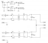
Both STKs will be running in non-inverting configuration, I built this circuit long time ago, and results were very good.
The first Opamp is connected as buffer only, while the second is configured as an inverting Opamp.
I have used the first Opamp as a buffer cuz I noticed that the inverting Opamp may add phase delay to the second STK, so I used the first Opamp as a buffer to add the same phase delay to the first STK, and obtain best possible results.
Also bear in mind that you don't have to bother your self by desiging another inverted STK circuit nor the PCB design, so that both STKs will be running as non-inverting amplifiers and they have the same electrical and frequency response charctersistics.
Regarding the power supply, note that each STK will be virtually driving 4 Ohm inductive load, not 8 Ohm. You better use 60+/- volts power supply, and each transformer must be capable of delivering 7.5 Ampere at least.
Look at the accompanying diagram please.
Regards
No need to change the original schematicccs of the STKs your are going to use.
Both STKs will be running in non-inverting configuration, I built this circuit long time ago, and results were very good.
The first Opamp is connected as buffer only, while the second is configured as an inverting Opamp.
I have used the first Opamp as a buffer cuz I noticed that the inverting Opamp may add phase delay to the second STK, so I used the first Opamp as a buffer to add the same phase delay to the first STK, and obtain best possible results.
Also bear in mind that you don't have to bother your self by desiging another inverted STK circuit nor the PCB design, so that both STKs will be running as non-inverting amplifiers and they have the same electrical and frequency response charctersistics.
Regarding the power supply, note that each STK will be virtually driving 4 Ohm inductive load, not 8 Ohm. You better use 60+/- volts power supply, and each transformer must be capable of delivering 7.5 Ampere at least.
Look at the accompanying diagram please.
Regards
Attachments
Don't use the schematic in the Datasheet.
Lower the gain to ~26 and take the inductor from the output.
In my opinion the best STK chip to bridge is the STK401-330 😉
You can bridge each chip( each one as 2 channels).
Lower the gain to ~26 and take the inductor from the output.
In my opinion the best STK chip to bridge is the STK401-330 😉
You can bridge each chip( each one as 2 channels).
Hi metal
I never tried to bridge amplifiers.
Would you please send me the schematichs that worked for the bridged stk amplifier.I have an amplifier with two channels: 2x stk4048 and I'd like to try out bridging them.
Please help me out maybe I understand that bridging.
Thanks
I never tried to bridge amplifiers.
Would you please send me the schematichs that worked for the bridged stk amplifier.I have an amplifier with two channels: 2x stk4048 and I'd like to try out bridging them.
Please help me out maybe I understand that bridging.
Thanks
Hello AudioIng
I have attached a schematic yesterday, showing how to connect Opamps to make bridging, plaes read all posts in this thread, and don't make any decisions untill you finish reading all posts.
If you still need further help, I will be here to give you a hand.
Metal
I have attached a schematic yesterday, showing how to connect Opamps to make bridging, plaes read all posts in this thread, and don't make any decisions untill you finish reading all posts.
If you still need further help, I will be here to give you a hand.
Metal
To Metal
Thanks for the advice.Reading all posts answered some open questions.There is still one question: where do I collect the output power from the bridged amplifier?
Maybe it is a dumb question but i have to ask it.
1.Do I connect the speaker between the outputs of the two stk ic's?
2.Or I connect the two outputs together in one point and the other point for connecting the speaker will be the ground?
Like I said it is the first time I bridge amplifiers.
Please don't be upset,take your time and give me an answer.
The schematic with the two tl op-amps is clear. One of the tl drives one stk and the other tl drives the second stk.
Thanks
AudioIng
Hello
You take the first output "Non - Inverted, and connect it to "+" terminal of your speaker, take the second output "Inverted" and connect it to "-" terminal of the speaker. Don't ever think about connecting both outputs together, as you are gonna blow the STKs, cuz they give inphase signal, but with opposite polarities.
So, no GND is connected to speaker, niether any outputs, ok 🙂
I am not upset, and rarely I do.
The schematic with the two tl op-amps is clear. One of the tl drives one stk and the other tl drives the second stk. Exactly 🙂
Regards
To Metal
Thanks.
All clear. 🙂
I try it out. I'm a bit affraid not to burn my speakers... it will be something near to 400W on the output.
I use my speakers with a Bose 1801: 250W/channel.
Let's see if the bridged stk amplifier delivers more. 🙂
Bye
Thanks.
All clear. 🙂
I try it out. I'm a bit affraid not to burn my speakers... it will be something near to 400W on the output.
I use my speakers with a Bose 1801: 250W/channel.
Let's see if the bridged stk amplifier delivers more. 🙂
Bye
Hello AudioIng
Good luck 🙂
Just don't turn the volume too high when it works. And you better add 10 Ohm 5 watt resistors on the supplies rails when you first carry the tests.
I know how it feels when the GC works perfectly, the person becomes too happy to the extent that he doesn't care if his speakers blow.
Keep me informed of what happens with you, ok 😉
STK4050 pcb's in PDF format
Well, here they are. With the updated EpressPCB file. A little late but...beter than never.
See ya!
metal said:Hello bubu
Can you please post the PCB as PDF file.
Thanks
Well, here they are. With the updated EpressPCB file. A little late but...beter than never.
See ya!
Attachments
- Status
- Not open for further replies.
- Home
- Amplifiers
- Chip Amps
- Bridging STK4048XI module is the best.