Absolutely, I use them on everything I build. They help to filter out power line noise. And be sure to use crimp connectors, not solder, for earth ground to chassis for safety. Crimp on spade lug connector for inlet filter, crimp on screw lug for chassis, and large enough wire guage to conduct full current in case of a fault condition.
Mike
Mike
Heatsink wise I have been calculating the thermal resistance and
halving the answer to ensure plenty of redundency, sounds good?
Hi,
Not really. You can't halve the chips thermal resistance so a heatsink
twice as big as it needs to be is simply twice as big as it needs to be.
It won't halve the chip temperature, only the heatsink temperature.
The whole point of using cheap chip-amps is using their capabilities.
TBH I'm not sure you know what that means. I'd say buy build and
learn from what I suggested earlier, you won't go far wrong.
rgds, sreten.
I and all of us will accept that doubling the heatsink size "can't halve the chip's thermal resistance".Not really. You can't halve the chips thermal resistance so a heatsink
twice as big as it needs to be is simply twice as big as it needs to be.
It won't halve the chip temperature, only the heatsink temperature.
The thermal resistance of the chipamp will be specified in the datasheet.
But you give the impression that increasing the size of the chipamp heatsink gives no advantage.
Is that another way of saying that decreasing the size of the chipamp heatsink gives improved performance.
Of course you're not saying that.
Let's take a typical chipamp with Rth j-c = 1C/W
Let's assume it has to dissipate an average power of 10W. (Is this a reasonable average dissipation assumption for a 68W into 8ohm amplifier operating at an average output power of 1W to 2W?)
We can immediately deduce that the average temperature of the junction (Tj) are ~10Cdegrees above the case temperature (Tc)
Now assume in the comparison (big sink to little sink) that Rth c-s is 2C/W for both set ups.
We can again deduce that Tc is 20Cdegrees above the heatsink interface temperature.
Now the crux of the disagreement.
We will compare a 3C/W Rth s-a sink (little sink) to a 1.5C/W Rth s-a (double size sink)
We have Ts (small) @ 30Cdegrees above ambient and Ts (double size) @ 15Cdegrees above ambient.
Let's finally assume that the ratings Rth s-a for both sizes of sinks have been determined (or measured) at that 10W dissipation in an ambient of 25degC. (this is a poor assumption and exaggerates the differences produced by the two sizes of sinks).
Tj (small sink) = 25 + 30 + 20 + 10 = 85degC.
Tj (double size) = 25 + 15 + 20 + 10 = 70degC.
That difference in average operating temperature will have an effect on the parameters of the chipamp. It will also have an effect on the way the protection inside the chipamp operates.
That difference in temperature will almost certainly be heard as a change of SQ coming out of the speakers.
One of the biggest problems with National's datasheets and app notes is that they rate everything at whichever extreme makes their chip seem very good.
In particular they adopt 25degC for some specifications/ratings and for other specifications adopt 150degC. We have to learn that simply accepting datasheet figures without taking account of operating temperatures will lead to poor modeling and poor predictions.
Do you want/need to do the numbers when the average output power of that 68W chipamp is increased to 8W to 16W? (~+9dB of SPL)
Last edited:
Hi,
My point was doubling the size of a sensibly sized heatsink does not help much.
I really can't see with Junction Max at 150C, and transient SOA max 250C,
any real differences between the 85C and 70C cases, they seem illusory.
I very much doubt at normal levels anyone could hear the difference.
rgds, sreten.
listen to how often "spike" and other protections interfere with the music signal.
The higher the chip temperature the worse this limiting seems to become.
If you run a chip with Tc/Tj at 150degC then just a tiny transient will limit.
That is a long way from Tj @ 85degC when a substantial transient should be able to pass before limiting sets in.
Now, lower the chip temp by a further 15Cdegrees and the transient allowed to pass should be even higher. It's the clipping of the music signal due to higher chip temperatures that leads to reduced SQ from the speakers.
listen to how often "spike" and other protections interfere with the music signal.
The higher the chip temperature the worse this limiting seems to become.
If you run a chip with Tc/Tj at 150degC then just a tiny transient will limit.
That is a long way from Tj @ 85degC when a substantial transient should be able to pass before limiting sets in.
Now, lower the chip temp by a further 15Cdegrees and the transient allowed to pass should be even higher. It's the clipping of the music signal due to higher chip temperatures that leads to reduced SQ from the speakers.
Hi,
I'm sorry but complete technical tosh. Yes, the one with the bigger heatsink
will play a tiny bit louder with the same sound quality as the one with the
smaller heatsink, but its nebulous, there are so many sound quality issues.
Most of the time at normal levels clipping issues should be irrelevant,
and there will be no audible difference in the effective level of quality.
If you want very high quality design it in, the OP I think cannot do that.
The best point about chipamps as here is the PS board + components,
+ 2 PA boards + components = a grand total of £22 delivered, great !
Design details are churlish, complete the above with cost effective design.
rgds, sreten.
IMO for a 68W 8 ohm AB amplifier around 2C/W is right, but for 16 ohm
1.5C/W would be fine, and it follows that around 1-1.5C/W for 4 ohms.
Last edited:
No thanks, for giving my argument consideration.I'm sorry but complete technical tosh.
I hear it on all the (single) chipamps I have built. They cannot play loud in comparison to what their Maximum Power Ratings would indicate. They appear to affect SQ well below voltage clipping. I have surmised that this reducing SQ, as level is moved up, can be due to current clipping/limiting.
But apparently that is
technical tosh.
Hi,
Not really. You can't halve the chips thermal resistance so a heatsink
twice as big as it needs to be is simply twice as big as it needs to be.
Turns out you can... by ordering the right Parts.
The non-isolated tab version of LM3886 is roughly half the thermal impedance.
AndrewT is correct about SQ and keeping temperature of the semi chip lower not inflicting SPIKE on transients when pushing chip amps hard. The insulated tab versions faster thermal time constant needs to be considered too.
see here http://www.diyaudio.com/forums/chip-amps/182687-improving-heat-transfer-ics-2.html#post2636980
Luckily with OPs 16 ohms speaker the heatsink requirements are much less severe than 4 ohms here http://www.diyaudio.com/forums/solid-state/179085-updating-dynaco-stereo-120-a-2.html#post2572021
Last edited:
Hmm... interesting discussion but at least I can stick with the ~2C/W approximation. And in the meantime I've got to the bottom of gain and GBWP, so I no longer have to rely on the questionable equation: A = ( SQRT (Po * Rl) ) / Vo. Oh and I'm getting the lm3886TF which looks to be the plastic version, at least heat shouldn't be a problem.
Sreten, in your schematic, what is the difference between 'speaker ground' and everything else which uses signal ground? Should the speakers just have a separate link to the ground star?
Sreten, in your schematic, what is the difference between 'speaker ground' and everything else which uses signal ground? Should the speakers just have a separate link to the ground star?
Last edited:
Erm, bit of an update. My speakers are 6 Ohm, not 16. 16 is for something else that can be connected.
And entering this into my excel doc suggests I can get lots of power, too much in fact for the chip. I could upload it here for someone to check all the forumlas? As I say if this all doesn't end in a fire, then I will probably do a guide outlining what I have learned to make it easier for people in the future and anything I include should be technically accurate.
Ok, so as long as I don't go mad with volume the amp should still be ok, even if the numbers suggest it could be run too hard?
Attachments
Hi Blue eagle,
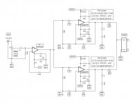
If you're interested, this is the amp section of my three way active setup that I use to drive my 6 ohm woofers. Please note there are several things that are critical for proper operation. First, except for the input cap it is fully DC coupled, so a speaker protection scheme of some sort is essential. Second, resistors specified as .1% are critical for lowerst possible output offset voltage, you can buy them that way or do what I did, buy a bunch and measure them yourself. Third, there are four separate grounds; (1) a small signal ground for the LM4562 and input side of the LM3886 amps, (2) a small signal power ground for the LM4562, (3) a large signal ground for the LM3886 speaker grounds, and (4) a large signal power ground for the LM3886, they are listed on the schematic with lower case charaters for small signal, and upper case charaters for large signal. I've been using this setup for many years and have never had a problem, and it performs very well.

Mike
If you're interested, this is the amp section of my three way active setup that I use to drive my 6 ohm woofers. Please note there are several things that are critical for proper operation. First, except for the input cap it is fully DC coupled, so a speaker protection scheme of some sort is essential. Second, resistors specified as .1% are critical for lowerst possible output offset voltage, you can buy them that way or do what I did, buy a bunch and measure them yourself. Third, there are four separate grounds; (1) a small signal ground for the LM4562 and input side of the LM3886 amps, (2) a small signal power ground for the LM4562, (3) a large signal ground for the LM3886 speaker grounds, and (4) a large signal power ground for the LM3886, they are listed on the schematic with lower case charaters for small signal, and upper case charaters for large signal. I've been using this setup for many years and have never had a problem, and it performs very well.

Mike
Thanks but I've already ordered the dual mono LM3886 kit from chipamp.com. I was thinking I could eventually build up to a 3 way active system but the problem is simply I don't know very much about the drivers I have, so there are probably loads of things that would be uncertain. This makes that a much longer term idea, one solution would be buying new speakers and that isn't going to happen for a few years.
Oh, could you explain how the separate grounds work though? Are they just separate stars, where do they all run to? I thought they could ultimately all be connected to earth from the mains, but if the signal ground from my input is not at the same level as earth, this would be bad news for the source?
Here ya go,
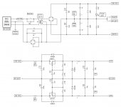
All grounds connect back to power supply through separate conductors. Many here will tell you it's OK to combine them and run a single conductor back to power supply, and while that may "work", to keep distortion to the lowest levels and minimize potential for ground loops, use separate conductors.

Mike
All grounds connect back to power supply through separate conductors. Many here will tell you it's OK to combine them and run a single conductor back to power supply, and while that may "work", to keep distortion to the lowest levels and minimize potential for ground loops, use separate conductors.

Mike
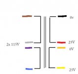
Hi, I'm having some trouble with my transformer. As seems to be recommending I am testing it all in stages and the first stage doesn't work, I just get 0V from the secondaries.
The diagram on the transformer is as the image attached. I've connected grey&violet together (Using 230-240Vac mains) and on the secondary side, black and yellow are connected.
I thought this should give:
black&yellow = 0V
Red = 25V
Orange = -25V
It has blown one fuse (2A slow-blow) but other times it has remained on for over a minute so I don't think there is a short anyway. Mains is definitely reaching the primary side so could it be a dodgy transformer?
Attachments
No, you need to connect the secondaries together at the red and orange leads to form a center tap which then connects to common ground.
Mike
Mike
Ah, I think connecting the black and yellow will have the same effect and I went for that in order to have 0v as black. Maybe I have a dodgy multi meter, it is also brand new...
Last edited:
Actually, now that I've read your post more carefully, you're right, it should work that way. There must be something else wrong if it's blowing fuses. Is it possible you're confusing the primary for the secondary and hooking the secondary to the mains? Using your ohmmeter check resistance of the windings, the primaries should read higher. Another possibility is you might have connected the primaries up out of phase. You can use a "light bulb tester" to check it out (you should be using the light bulb tester for all powered testing anyway).
Mike
Mike
Thanks for the suggestions, I tried the resistance of each side and the primaries read several ohms above the <1Ohm of the secondaries.
After googling, a 'bulb tester' is a standard light bulb wired in series with the live mains cable?
Another experiment went a little awry when I connected the multimeter in ammeter mode across one of the secondaries, this caused a large enough current to burn a track off the pcb inside the multimeter. So maybe the multimeter is just not reading the voltage? (and I am using Vac mode) because it is obviously there to cause a large current to flow.
I agree with Mich, always use a bulb tester when powering a new or modified mains powered project.
Even just a simple mains transformer.
The resistance of the bulb filament stops excessive current flowing into shorts and wiring and component errors. It even stops you blowing the mains fuse when the transformer is a direct short across the mains.
Even just a simple mains transformer.
The resistance of the bulb filament stops excessive current flowing into shorts and wiring and component errors. It even stops you blowing the mains fuse when the transformer is a direct short across the mains.
- Status
- Not open for further replies.
- Home
- Amplifiers
- Chip Amps
- Bridged chipamp for 16Ohm speakers
