Cool, thanks very much that clears up loads of little things and looks doable using the chipamp kit.
What is with the crazy psu layout though? Could I run something like the attached design, just with your values? I think it would be a fiddle to modify the kit board to match that design.
And the inductor, that is a home made one made by wrapping wire around that resistor?
What is with the crazy psu layout though? Could I run something like the attached design, just with your values? I think it would be a fiddle to modify the kit board to match that design.
And the inductor, that is a home made one made by wrapping wire around that resistor?
The power supply design isn't set in stone, feel free to substitute as you please, the one supplied with the kit should work fine, that schematic is for an amp I built for a friend several years ago.
The output inductor should be wound over a resistor made from non-magnetic materials, that's why a carbon composition resistor is specified, but it doesn't really need to be wound around anything at all, just wind around something like a pencil to form a nice coil and connect it separately, but avoid placing near anything magnetic.
The main reason I posted that design was to give you a good idea of what is needed at minimum to avoid problems. Many beginners don't understand that the so called "optional components" are really mandatory for making a stable and well working amp.
Mike
Not sure if you know this application note from National Semi:
http://www.national.com/an/AN/AN-1192.pdf
It basically deals with the LM3886 but the circuits described here may also work with the LM3875 if you take into account that LM3886 can handle 4 Ohm loads and LM3875 is only intended for 8 Ohms. Your loudspeaker has a nominal impedance of 16 Ohms so you can use 2x LM3875 in bridged mode and won´t overload the LM3875.
This application note explains everything you need to know when you want to build a bridged amp.
Easy way out , Use this Spreadsheet.www.national.com/assets/en/tools/Overture_Design_Guide15.xls
Cheers mike, that looks very possible with the kit PSU and maybe a few additions like the power LED.
I was wondering about a capacitor in series with the speaker. AndrewT mentioned that DC coupling should be avoided and my understanding is this translates to a series capacitor which will block DC signals (I've read severe warnings about DC coupling so I'll agree to this one!).
The NS datasheet for that chip suggests the arrangement you have (700uH//10Ohm) and a 4700uF 50V. However surely these will resonant at 550Hz, removing the DC blocking around that frequency? The datasheet suggests the resistor will reduce the Q factor the "series resonant circuit due to the capacitive load"
So... does this mean, C blocks dc, L blocks the high frequency and R is to minimize the effect of resonance between these two reactive components? Ultimately, NS have your arrangement with another capacitor in there, so this is ok?
Do I even want my high frequencies attenuated? The inductor hits 21ohms at 5khz :S
Last edited:
Are you planning to build the single supply version? If not, don't put a cap on the output of the amp, the DC coupling AndrewT was refering to was for the input of the amp and on the feedback network, where the 1uF and 100uF caps are on the schematic I posted. And I went back and took a look at the inductor value on the schematic, it should be .7uH, not 700uH, I'm not sure how that happened. Sorry for the confusion.
Mike
Mike
Ah great, it would resonant at 300Mhz, I can live with that lol. Suppose it would have been a push to get 700uH from a few turns on a resistor.
I was planning on a single PSU to run both but I've also read an electrolyic cap on the output degrades quality, so I would be happy to forgo that and get another PSU. I hope the same transformer can run both? And is it then better to run a PSU to both left channel amps and vice versa (since they will be dealing with identical signals)
Oh and the ring at the input to that amp, that is a ferrite?
Not a ferrite, a shielded cable. For that amp I mounted the volume and balance controls near the rear panel and used shaft extensions for the front panel knobs. I urge you to go with a split supply, it makes things a lot simpler and in my opinion sounds better without the cap in the output. What is the transformer you were planning to use?
Mike
Mike
Probably a 225VA 230Vac +/-25V but the 300VA version is also an option. I reckon it will draw 97VA per channel maximum.
what is +-25V?225VA 230Vac +/-25V
Is that AC from the secondary (0-25Vac, 0-25Vac) or DC from the PSU (dual polarity +25Vdc, 0, -25Vdc)?
When you get your transformer it is worth checking the open circuit secondary output voltage and the corresponding supply voltage to ensure that your PSU is within 82Vdc when mains rises to max tolerance.
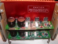
You can purchase something like this off ebay. Its out of a Rock-ola Bubbler Jukebox. It has the cover removed as well as the computer controlled preamp.
Each module contains one channel of unbridged power. It also has one channel of bridged power. A module for each channel right and left. It has the capability to provide 60 watts stereo per channel and 120 watts bridged per channel.
All you add is a AC supply and signal and take off output to the speakers.
Attachments
Last edited:
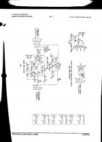
Hi 6BG6GA, that diagram shows one channel wired for parallel operation, not bridged, and it would only provide a nominal 120 watts into a 2 ohm load. Beyond that, it's a rather strange way to parallel these things; different feedback circuits for each one which could lead to unequal currents through the output summing resistors, and one amp output is driving the input of the other which is not the optimal way to do it. I would recommend steering clear of this design.
Mike
Mike
Last edited:
Ok, I just realized there are two amp assemblies there that could be bridged, but I stand on what I said about the design, I don't like it.
Mike
Mike
Quote:
Ok, I just realized there are two amp assemblies there that could be bridged, but I stand on what I said about the design, I don't like it.
I don't know what to say.... It works well for Rock-ola. It sound good in my Rockola Bubbler Juke box.
The amplifiers sound identical to the chip amps that I made.
Well the thing putting me off the rock-ola is that it comes pre-built. I'd like to have a hand in the design and then put it all together, for the same sort of money I could probably get a pretty decent commercial amp but I prefer the diy route.
Heatsink wise I have been calculating the thermal resistance and halving the answer to ensure plenty of redundency, sounds good? Otherwise I think I'm happy with the design, now I'll think about the chassis (the hard part!). Thanks for the help guys, I'm sure I'll pop back in with news (If it all doesn't explode and burn I might even do a tutorial type post)
Heatsink wise I have been calculating the thermal resistance and halving the answer to ensure plenty of redundency, sounds good? Otherwise I think I'm happy with the design, now I'll think about the chassis (the hard part!). Thanks for the help guys, I'm sure I'll pop back in with news (If it all doesn't explode and burn I might even do a tutorial type post)
Last edited:
Back already 😉Not a ferrite, a shielded cable. For that amp I mounted the volume and balance controls near the rear panel and used shaft extensions for the front panel knobs. I urge you to go with a split supply, it makes things a lot simpler and in my opinion sounds better without the cap in the output. What is the transformer you were planning to use?
Mike
You said a split PSU would be much better an allow me to forgo a capacitor in series with the speaker, but why? The series cap there is to stop dc, so it must somehow control and reduce dc bias of the output? I can't see what it will do other than make the bass a little better by increasing the total capacitance of the supply system.
The whole idea behind using the split supply along with AC coupling the input and feedback network is to minimize DC offset at the output. Many here, but not all, would argue that having a cap at the output will degrade the sound of the amp due to the large currents in the output circuit. Using the split supply also simplifies the design by eliminating the need to generate an artificial ground for the input and feedback network.
Mike
Mike
- Status
- Not open for further replies.
- Home
- Amplifiers
- Chip Amps
- Bridged chipamp for 16Ohm speakers