Ah, I'm having some problems with the power dissipation calculation. The datasheet equation is: Pdmax = Vcc^2 / 2*pi^2*Rl
With Vcc = 32, Rl = 16 this gives 3.2W which surely can't be correct? It contradicts the dissipated vs output power graphs. I don't know what is wrong because that is the datasheet equation... ?
I've decided I'll sacrifice a bit of power and go with the LM3886 kit because it comes with 10,000uF caps and a volume control already designed in so I shouldn't need to change anything. Just need to calculate the heatsink and transformer requirements.
Last edited:
You aren't working the math correctly. Start with TOTAL supply voltage (64v in your case) squared = 4096 /(2 * Pi squared * 16ohms) = 12.97 watts dissipated.
Mike
Whoops, you worked it correctly but with wrong supply voltage.
Mike
Whoops, you worked it correctly but with wrong supply voltage.
Last edited:
That's the power that the chip sends to the heatsink.
The max output voltage is ~[Vcc -8]/2 ~28Vpk
Maximum power will be down on that due to supply rail sag. For 16ohm speaker allow 3volts sag/supply rail.
Max sinewave power is ~ 25^2 /32 ~ 20W into 16r
Note that dissipated power is ~ 65% of the maximum output power. and note also that the dissipated stays up around the 13W level while output is >40% of maximum output power, i.e. @ 8W output the chip still runs hot. It's not until the average output power is below a watt that the chip gets a chance to run cool.
That one watt into 8ohm, 88dB speakers sounds quite loud. You might get a big surprise to discover that your average listening power into your 16ohm speaker is ~100mW
Since you have 16ohm speaker it might be worth pushing the PSU to closer to the maximum the chip can accept.
In the UK you will find that a 230:25+25Vac does not take a chipamp to it's maximum 84V rating when the mains is at 254Vac.
230:26+26 or maybe even 230:27+27Vac might just about run the 3886 chipamps, if the transformer regulation is low (say 5%).
Last edited:
Sounds good to my ears! (yea, you've probably heard that a hundred times, sorry 😉)
Ok, revised numbers:
+\-33V 300VA 6%Vreg
Pdmax = 14W
Vomax = 29V
Pomax = 21W (includes 3V drop from 29)
Iomax = 1.7A
Sink thermal resistance: 6.8 oC/W
This gives 48VA per channel, total ~100VA so maybe I could get away with a 160VA transformer (these only come in 30V, so psu load would drop again). Or move up to 230VA +\-35V?
Also, I'll probably exaggerate the heatsink choice as well (to allow for additional amps, or if it runs really hot, I'll scrap the additional amps idea)
I'm not clear about your thoughts on transformer secondary voltage, but I would recommend nothing higher than 27 VAC to be safely conservative. Be aware that mains voltage can run high, along with variance for transformer regulation, you could end up exceeding +/- 42 volt maximum with anything higher than that. I personally never use anything higher than 25 VAC, the extra margin won't sacrifice much power, and will provide peace of mind.
Mike
Mike
Well again I'm worried about power lol. Dropping to +\-27V would give me 12.5W per channel, a far cry from the 80W was hoping for the other day 🙁 Unless you can convince me that is enough to run these speakers? Tbh I rarely blast them but I wouldn't want it to be underpowered (so that the amp is run hard all the time) and like to have plenty in reserve.
Btw, what is Vin likely to be? I'll be plugging in a PC and xbox. Wiki says consumer 'line level' is 0.316Vrms but I read that it is a grey area and can vary quite a lot. It matters for the gain equation, to keep the gain in 20-200 as suggested. I also intended to use a 25K pot, as shown in the kit schematic, as a volume control and I'm unsure if this will be very loud or very quiet...
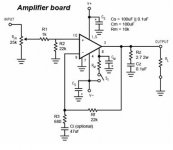
edit: Chipamp.com schematic attached for quick reference.
Btw, what is Vin likely to be? I'll be plugging in a PC and xbox. Wiki says consumer 'line level' is 0.316Vrms but I read that it is a grey area and can vary quite a lot. It matters for the gain equation, to keep the gain in 20-200 as suggested. I also intended to use a 25K pot, as shown in the kit schematic, as a volume control and I'm unsure if this will be very loud or very quiet...
edit: Chipamp.com schematic attached for quick reference.
Attachments
Last edited:
I think you are confusing AC & DC voltages.
Transformers put out AC.
Chipamps need a DC supply.
The 3886 absolute limit for powered up Supply Voltage is 84Vdc.
The dual polarity supply rails must never exceed +-42Vdc when ever there is signal present.
A 25+25Vac transformer after rectification and smoothing gets well under that +-42Vdc @ nominal mains supply voltage. At maximum Mains supply voltage the 25Vac transformer approaches that 84Vdc limit.
A little leeway is left and that's why I suggested trying 26Vac or even 27Vac.
Using either of these leaves virtually no factor of safety on overvolting the chip.
16ohms speaker puts less load on the chipamp. That in my opinion allows one to approach the absolute voltage limits, but not exceed them.
I use gain of ~27 in many of my amps.what is Vin likely to be? I'll be plugging in a PC and xbox. Wiki says consumer 'line level' is 0.316Vrms but I read that it is a grey area and can vary quite a lot. It matters for the gain equation, to keep the gain in 20-200 as suggested. I also intended to use a 25K pot, as shown in the kit schematic, as a volume control and I'm unsure if this will be very loud or very quiet...
I use a buffer, rather than a pre-amp with gain, some of my sources cannot drive my amps to maximum output. FM radio only takes my chipamp to a maximum of ~-12dB ref maximum power. It plays OK as non-serious music listening.
In the main listening areas, I arrange that all sources can drive the output to maximum levels, but generally listen at average levels of -30dB to -20dB ref max output. I find that plenty loud enough.
It is very simple to change a few component values to alter the gain of a chipamp, (leave room on the PCB for access to make changes if required).
That schematic you have shown again is not suitable as a beginner project.
You need an AC coupled design that includes all the National "optional" components to give beginners the best chance of building a successfully operating amplifier that is less likely to blow up and maybe more importantly reduce the risk of damaging your speakers.
Yep you'd be correct there. I had just been going off +/-30V means Vcc is 60V and therefore I have 24V of headroom.
Is there an easy conversion? Some googling suggested Vac = 1.8 * Vdc but this doesn't seem right.
Edit, just seen your new post: I'm pulling my hair out now lol. I wanted a kit because the parts are cheaper from canada and the pcb's are both well designed and again cheaper than custom boards. Assuming you use PCBs, where do you get them from in the UK? I don't mind designing my own but I need to get a solid design sorted first and properly understand each bit. If I did my own board then I can lift the circuit exactly as is from the NS datasheet, perhaps using a PSU kit from chipamp.com.
Or there is the option of veroboard, but it seems like it might harder to have a star ground and my track width is limited by the board.
A buffer is something I haven't looked into yet but the NS circuit has a 10k pot on it, so again keeping the circuit exactly the same it should work?
Last edited:
output voltage from a transformer is
Mains input voltage / nominal rated voltage * secondary rated voltage * [1+transformer regulation] +- manufacturer's tolerance.
eg.
230:25Vac 6% regulation used on a 240Vac UK supply will output
240/230*25*[1+0.06] = 27.65Vac from each secondary winding when measured open circuit.
Now let's convert that to DC via bridge rectifier and smoothing capacitor.
Maximum voltage before the rectifier is the peak of the sinewave. Peak Voltage of sinewave = Vac * sqrt(2) = 27.65 *1.414 = 39.11Vpk.
The bridge rectifier when feeding an open circuit load will drop ~500mV/diode. The capacitor will charge up to 39.11-[2*0.5] ~38.1Vdc.
Now attach a quiescent current draw of a typical chipamp.
The diode bridge Vdrop will increase to ~700mV/diode giving a peak capacitor voltage of ~37.7Vpk. The capacitor will discharge slightly between charging pulses. Allow say 1Volt of discharging droop. The average voltage supplied to the chipamp is ~37.7 - half the droop (ripple voltage).
At 240Vac the chipamp will see ~37.2Vdc.
Now increase the mains voltage to the maximum tolerance of the UK mains system, i.e. 254Vac.
The chipamp will have a supply of ~39.5Vdc.
If instead of using two bridge rectifiers (one to each secondary) you use a single bridge rectifier shared across the dual secondary (centre tapped secondary) the maximum voltage delivered to the quiescent chipamp will increase by ~700mV to ~+-40.2Vdc (80.4Vdc).
This is well below the 84Vdc absolute limit for a 3886.
That is why for your 16ohms speaker I suggested a 26Vac or 27Vac transformer, to get as close to the 84Vdc limit without exceeding it.
You may be lucky and find a 240:28+28Vac transformer which when you do the calculation and check by measuring that it too lands just inside the 84Vdc limit.
Final note.
The highest voltage from a 230:25+25Vac 6% regulation transformer into a quiescent chipamp on a UK supply is ~40.2Vdc. This happens to have a factor of 1.61* Vac. Do not rely on this approximation. It varies a lot with Vac and with regulation.
Whoever wrote factor ~1.8 did not know what he was writing about.
Last edited:
Hi,
16 ohm 3 way speakers ? Very unusual ....
What resistance measures across the input terminals ?
IMO your best bet is to build a standard 8 ohm amplifier for a chip-amp.
(i.e. use an 8 ohm chip or bridge 4 ohm capable chips, bridging 8 ohm
chips is not a good idea at all, its something waiting to blow up.....)
If building a chip-amp for 8 ohm speakers I'd go for a "4 ohm design",
speakers are not resistors, this affects the power dissipation limits.
An 8 ohm amplifier would be more general purpose, and you could
be content knowing it will be stressed less driving 16 ohms.
rgds, sreten.
Last edited:
Wow, ok big revelation, it makes much more sense now. I've updated my excel doc so it can recalculate everything when I change the inputs.
As for the resistance across the terminals I can't actually tell you because the speakers are in my house in Leeds while I am in London for the summer, plan is to design this as a mini summer project and build it on my return.
To meet the current requirements of the transformer I will indeed need a 300VA one so this means 25V is the best choice, the next step is 30 and that is too much for a number of reasons. This also points to about 40W per channel which makes me happy again lol 🙂 Gain becomes 25.
Still not sure about custom PCB's, just got a couple of quotes and for the size I would need they would cost £80-£100 🙁
Last edited:
1 LM3886TF amplifier AMP+RECTIFIER FILTER BOARD DIY KIT | eBay
Hi,
The bits above are dirt cheap. Note you are not building a laboratory
amplifier, a music amplifier simply does not need as big a supply.
There is little point in oversizing the transformer, or the heatsinks.
~ 200VA should be fine, size the heatsinks properly to the package.
16 ohm speakers will be more than fine with ~ 160VA.
rgds, sreten.
http://www.chipamp.com/docs/lm3886-manual.pdf
Last edited:
Hi,
build this chipamp properly and it will double up as an 8ohm capable amplifier.
Assume it will have a maximum output of 68W into 8r0.
That can then be used to determine the transformer size for a pair of chipamps driving stereo into a pair of 8ohm speakers.
Total maximum power = 136W.
Recommended VA for that 136W total is 136VA to 272VA. (yes, 1times to 2times the max power).
Choose any toroid from 160VA to 300VA. All will work well.
For sole 16ohm use, the smaller transformers are perfectly adequate.
Hmm, what is it that concerns you about the chipamp.com design Andrew? The problem I have with the ebay one is there is no circuit diagram or parts list (until it've bought it) so I'm not sure what I'm getting. At least the chipamp one has panasonic caps, the boards look good and lots of people on here have used them. (And it comes with a potentiometer which I keep mentioning). The ebay one is cheap in fairness, half the price of the other one, so could be worth a punt at £22, just worried the quality might be dubious.
If I go to 225VA there is a 28Vdc option but that would run 90V with 254Vac and that assumes it meets the stated regulation and isn't worse. Erring on the side of caution makes me think 25V is fine now that I've got my sums right.
If I go to 225VA there is a 28Vdc option but that would run 90V with 254Vac and that assumes it meets the stated regulation and isn't worse. Erring on the side of caution makes me think 25V is fine now that I've got my sums right.
Last edited:
Is that 28Vac 225VA transformer a 230:28+28Vac?
If it is, then on UK mains it will overvoltage the 3886.
If it is, then on UK mains it will overvoltage the 3886.
Last edited:
forget cost for the moment.Hmm, what is it that concerns you about the chipamp.com design
Look at the National datasheet. Look for all the "optional" components. Read what each does. DO NOT OMIT the optional components.
DO NOT build a DC coupled nor a mixed AC & DC coupled amplifier.
Do a search on builders problems with National chipamps. Many of the problems are directly attributable to missing out one, or more, of the "optional" components.
I'm looking at transformers here And yea it looks like 230:28+28V
DC coupled amps: point taken, capacitor in series with the speaker. The single supply circuit in the datasheet suggests 4700uF 50V? (and parallel resistor+inductor look useful in stopping high frequency resonance)
Not quite sure what a mixed amp is though?
Looking at the kit circuit and the NS circuit I reckon I could chuck away any small components that have different values and use the values from the datasheet (just keeping things like the 10mF caps and amps themselves). In other words, if it looks like fig1 page1 would it be suitable?
Last edited:

- Status
- Not open for further replies.
- Home
- Amplifiers
- Chip Amps
- Bridged chipamp for 16Ohm speakers