Re: Re: ....Bridge/paralell ...
😕
Have tried trim-pots for nulling DC-offset, but something does not add up....
I did de-solder the output-resistor, and null each chip (some variation here), checked and fine-tuned after 30min.
Then re-soldered, and now I have ~20mV ? 😕
It seems that there is a difference when adjusting towards ground and between chips. What gives?
As mentioned...the production-spread among these chips are larger than life...
Arne K
Re: Re: Re: ....Bridge/paralell ...
Koinichiwa,
First, Jeff Rowland uses 0.5R Output Resistors, worth going up to anyway.
Secondly, I suspect there are some interactions between the chips. Try nulling offsets with the chips connected normally and repeat a few times while the Amp settles it's temperature. It is clear that JR does not employ Servos (he seems to share my dislike for their sound) and if he can so shall we DIY'ers.
Sayonara
Koinichiwa,
Cobra2 said:😕
Have tried trim-pots for nulling DC-offset, but something does not add up....
I did de-solder the output-resistor, and null each chip (some variation here), checked and fine-tuned after 30min.
Then re-soldered, and now I have ~20mV ? 😕
It seems that there is a difference when adjusting towards ground and between chips. What gives?
As mentioned...the production-spread among these chips are larger than life...
Arne K
First, Jeff Rowland uses 0.5R Output Resistors, worth going up to anyway.
Secondly, I suspect there are some interactions between the chips. Try nulling offsets with the chips connected normally and repeat a few times while the Amp settles it's temperature. It is clear that JR does not employ Servos (he seems to share my dislike for their sound) and if he can so shall we DIY'ers.
Sayonara

Re: am I right?
Koinichiwa,
Wrong. In your case use a 470K (18 turn) Pot. in all seriousness, for your schematic a dead short ot 22k will make little difference.
Sayonara
Koinichiwa,
popes said:offset null..
am i right?
Wrong. In your case use a 470K (18 turn) Pot. in all seriousness, for your schematic a dead short ot 22k will make little difference.
Sayonara
Re: thanks, Kuei Yang Wang
Koinichiwa,
If you like the sound of th OPA's /
YOU will need around a 10K multiturn offset trimmer, as you do not employ a DC blocking capacitor in the input to each chip.
Sayonara
Koinichiwa,
popes said:what do you think about my project?
opa548 3pararel bridge(use 548 6ea for one chanel )
If you like the sound of th OPA's /
popes said:i will use input R 6.2K ohm
feedback 100K ohm
offset null 470K ohm (multi turn)
YOU will need around a 10K multiturn offset trimmer, as you do not employ a DC blocking capacitor in the input to each chip.
Sayonara
dc blocking capacitors
i will use input transformer lundhal 1544A
if use transformer , is the DC block capacitor necessary?
thanks Kuei Yang Wang
i will use input transformer lundhal 1544A
if use transformer , is the DC block capacitor necessary?
thanks Kuei Yang Wang
Re: dc blocking capacitors
Koinichiwa,
No, but leaving it out means the value of your offset trim resistor changes, that's all.
Sayonara
Koinichiwa,
popes said:i will use input transformer lundhal 1544A
if use transformer , is the DC block capacitor necessary?
No, but leaving it out means the value of your offset trim resistor changes, that's all.
Sayonara
Re: another question..
Koinichiwa,
Hey, I forgot, the OPA's are FET input I think, so you cannot null the offset the same way as on the LM3875/3886. Simply use 0.47/0.5R output resistors, ground the non-inverting input and hope for the best.
If they are not FET Input your Pot needs to be around twice the value of all the resistors that are not DC blocked on the inverting input in paralell, so in your case 6k2//220k*2 = 12k - NPV is 10k.
Sayonara
Koinichiwa,
popes said:😉???
how much value need for me??
Hey, I forgot, the OPA's are FET input I think, so you cannot null the offset the same way as on the LM3875/3886. Simply use 0.47/0.5R output resistors, ground the non-inverting input and hope for the best.
If they are not FET Input your Pot needs to be around twice the value of all the resistors that are not DC blocked on the inverting input in paralell, so in your case 6k2//220k*2 = 12k - NPV is 10k.
Sayonara
Re: Re: another question..
i using opa541, what value should i use to zero the offset?
Kuei Yang Wang said:Koinichiwa,
Hey, I forgot, the OPA's are FET input I think, so you cannot null the offset the same way as on the LM3875/3886. Simply use 0.47/0.5R output resistors, ground the non-inverting input and hope for the best.
If they are not FET Input your Pot needs to be around twice the value of all the resistors that are not DC blocked on the inverting input in paralell, so in your case 6k2//220k*2 = 12k - NPV is 10k.
Sayonara
Mad_K said:547/8/9 have bipolar inputs. opa541 have fet input
i using opa541, what value should i use to zero the offset?
Koinichiwa,
Yeah, Sure. But it adds a load of components and potential noise sources. Other than that - it will work for any chip, J-Fet input or not.
Sayonara
Cobra2 said:Maybe this can be used? :
Arne K
(BB - APPLICATION BULLETIN - sboa046.pdf)
Yeah, Sure. But it adds a load of components and potential noise sources. Other than that - it will work for any chip, J-Fet input or not.
Sayonara
Output:
Just wondering what kind of output values you are expecting to get out of these circuits.
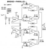
I know that the app notes from national state ~100W out of the bridged and the paralleled versions, and ~200W out of the bridged/parallel version. Although I think that they specify +-40V for their power supply.
Wes
Just wondering what kind of output values you are expecting to get out of these circuits.
I know that the app notes from national state ~100W out of the bridged and the paralleled versions, and ~200W out of the bridged/parallel version. Although I think that they specify +-40V for their power supply.
Wes
output
the output of a bridged cricuit into an 8 ohm load will be about 2x the rated output of the original non-bridged circuit into a 4 ohm load, generally speaking. so if your original circuit got 30wpc into 4ohms, it'll now put out 60wpc into 8 ohms. problem is that this rule applies to lower impedances as well, where you'll be more current limited than anything else.... so bridging is not recommended if you have low impedance speakers, unless you parallel devices to compensate.
the output of a bridged cricuit into an 8 ohm load will be about 2x the rated output of the original non-bridged circuit into a 4 ohm load, generally speaking. so if your original circuit got 30wpc into 4ohms, it'll now put out 60wpc into 8 ohms. problem is that this rule applies to lower impedances as well, where you'll be more current limited than anything else.... so bridging is not recommended if you have low impedance speakers, unless you parallel devices to compensate.
Re: Re: Re: another question..
as i havent had any feedback, i have ordered 2 5k 22-turn presets. if i have the non-inverting input connected to ground dirrectly now, why would a 200k+ preset be used? i would have thought that 5k was to much, and that i would not be able to zero offset accuratly. i will post the results of my test here.
Matttcattt said:i using opa541, what value should i use to zero the offset?
as i havent had any feedback, i have ordered 2 5k 22-turn presets. if i have the non-inverting input connected to ground dirrectly now, why would a 200k+ preset be used? i would have thought that 5k was to much, and that i would not be able to zero offset accuratly. i will post the results of my test here.
bridgeclone impression - worth the trouble?
how're the bridgeclones going fellas? i'm going to build a quad-channel gainclone of some sort or other, partly for fun, partly for experimenting with biamping, mostly to use eventually for the rear speakers in my surround setup. like others i have been dabbling with the idea of a bridged version. the extra power into higher-impedance loads is an obvious benefit, but i'm more interested in improvements in quality than quantity. can anyone comment on how a "properly implemented" bridgeclone compares to a single-ended version (e.g. Peter's)?
my own idea is to use a "proper" input transformer to derive the balanced signal, followed by a two standard single-ended gainclone circuits in complementary (bridged) fashion. i hesitate to call this a "balanced" amplifier as it does not have any intrinsic CMRR (it's left to the final load - the speaker - to sort that out), but i have heard from a few people that this is the best sounding way to go anyway. does using gainclone in this manner have any implications for circuit stability or final sound quality? would be very interested in some opinions on the matter. i did search thru the various threads for such answers, but it seems that most people attempting "bridgeclone" had not reached the development stage Peter is at with his design. Kuei Yang Wang, any thoughts? 😉
cheers,
dorkus
Re: bridgeclone impression - worth the trouble?
i am in the construction stage of my proper amplifier, using bridged, and bridged and paralleled. i have tested bridged, and bridged and paralleled, using the DRV134 IC to get the balanced input. i am using the OPA541 and OPA549 (8 of each) to get 4x bridged (OPA541) and 2x bridged and paralleled (OPA549). it is documented (not very well 😀) on my website: http://www.freewebs.com/matttcatttweb/index.htm have a look 😀
dorkus said:how're the bridgeclones going fellas? i'm going to build a quad-channel gainclone of some sort or other, partly for fun, partly for experimenting with biamping, mostly to use eventually for the rear speakers in my surround setup. like others i have been dabbling with the idea of a bridged version. the extra power into higher-impedance loads is an obvious benefit, but i'm more interested in improvements in quality than quantity. can anyone comment on how a "properly implemented" bridgeclone compares to a single-ended version (e.g. Peter's)?
my own idea is to use a "proper" input transformer to derive the balanced signal, followed by a two standard single-ended gainclone circuits in complementary (bridged) fashion. i hesitate to call this a "balanced" amplifier as it does not have any intrinsic CMRR (it's left to the final load - the speaker - to sort that out), but i have heard from a few people that this is the best sounding way to go anyway. does using gainclone in this manner have any implications for circuit stability or final sound quality? would be very interested in some opinions on the matter. i did search thru the various threads for such answers, but it seems that most people attempting "bridgeclone" had not reached the development stage Peter is at with his design. Kuei Yang Wang, any thoughts? 😉
cheers,
dorkus
i am in the construction stage of my proper amplifier, using bridged, and bridged and paralleled. i have tested bridged, and bridged and paralleled, using the DRV134 IC to get the balanced input. i am using the OPA541 and OPA549 (8 of each) to get 4x bridged (OPA541) and 2x bridged and paralleled (OPA549). it is documented (not very well 😀) on my website: http://www.freewebs.com/matttcatttweb/index.htm have a look 😀
- Status
- Not open for further replies.
- Home
- Amplifiers
- Chip Amps
- Bridgeclone