Aunkst said:I think this is an excellent question. I don't have the printed boards, but just how easy is it to bridge two amps together?
I'm learning alot, but some of the finer details excape me at this point.
I would hold out on this project for now, unless you have access to lab equipment. I am going to go into lab within the next week, and prototype a bridgeclone with my boards, and the DRV134 chips (see above posts for some details). My initial assumption is that with matched components on the boards and a 0.22ohm output resistor, it should work fine with the DRV134 chip, but I will verify this in lab with a scope, and do some testing.
--
Brian
That's exactly what I was thinking Brian. As long as the components are well matched, it should work fine. I was planning on putting one together in this configuration sometime this week. I have a scope at work, and can check for oscillations. I'll have to let you know how it goes.
Cheers,
Zach
Cheers,
Zach
ok, i guess that pretty much answers my question. i wasnt sure if it was that easy (well, sorta), but i guess it seems its pretty possible if everything is pretty well matched. looks like i gotta get rid of those occasional radio shack resistors (gasp....i had messed up with one on each board...)
BrianGT said:
I would hold out on this project for now, unless you have access to lab equipment. I--
Brian
Ahh, But I do have access to a good scope, (1st year EE student). lay some procedure on me,
youre' saying:
1. build both sides with matched components.
2. test each side independantly.
3. use resistors to set output current EQUAL.
4. use a DRV134 to split the phase and drive each side of the bridge.
sounds simple.
when I am scoping for oscillation, what would I look for?
Aunkst said:Ahh, But I do have access to a good scope, (1st year EE student). lay some procedure on me,
youre' saying:
1. build both sides with matched components.
2. test each side independantly.
3. use resistors to set output current EQUAL.
4. use a DRV134 to split the phase and drive each side of the bridge.
Sounds like you have it covered. I would just input a sinusoid from a functional generator and verify that you have a clean output, checking the gain, and the level of power output obtained under load.
--
Brian
BrianGT said:
Sounds like you have it covered. I would just input a sinusoid from a functional generator and verify that you have a clean output, checking the gain, and the level of power output obtained under load.
--
Brian
What kind of sine wave do you get from a Non Functional generator?
🙂 🙂
Anthony
So did any of you guys get around to prototyping a bridge clone of sorts?
I have seen the BPA with 6 chip's and the PA100 floating around. Any others?
I have seen the BPA with 6 chip's and the PA100 floating around. Any others?
Hey, I decided on the LM3875 gainclone from this site.
http://stiftsbogtrykkeriet.dk/~mcs/LM3875/index.html
I was wondering if anyone had a parts list for it? Thanks
-Steve
http://stiftsbogtrykkeriet.dk/~mcs/LM3875/index.html
I was wondering if anyone had a parts list for it? Thanks
-Steve
if you are going to build this, don't attempt Vectorboard, you definitely need a PCB (the pins themselves are only 20 mils, the spacing is quite compact):
this is a "fair" idea of what the PCB should look like:
I've had some proto's burned, they just arrived so haven't been tested.
An externally hosted image should be here but it was not working when we last tested it.
this is a "fair" idea of what the PCB should look like:
An externally hosted image should be here but it was not working when we last tested it.
I've had some proto's burned, they just arrived so haven't been tested.
populated board
here's the board -- with humongous PP caps:
here's the board -- with humongous PP caps:
An externally hosted image should be here but it was not working when we last tested it.
New Boards
they just arrived so I wired one up:
they just arrived so I wired one up:
An externally hosted image should be here but it was not working when we last tested it.
here's a graph of the proto-Bridgeclone and the newer version --
changes -- the snubber resistors were changed to 5.6R from 2.7R, the layout is a little cleaner -- the power supply for both test amplifiers were identical. the distortion at 1kHz was 0.0019%, up a tad from the first run.
An externally hosted image should be here but it was not working when we last tested it.
changes -- the snubber resistors were changed to 5.6R from 2.7R, the layout is a little cleaner -- the power supply for both test amplifiers were identical. the distortion at 1kHz was 0.0019%, up a tad from the first run.
What is abundantly clear after testing this amplifier at 100 watts is that you can't kid around with the heatsinking of the chip in the bridged version. Machine screws are not sufficient to get the best contact between the chip and heatsink -- you have to use a fixture which compresses the chip against the sink and thermal grease.
Attachments
Care to Share your board design??
jackinnj would you consider posting your pcb design so that I (we) could give it a shot?
Mark
jackinnj would you consider posting your pcb design so that I (we) could give it a shot?
Mark
the schematic follows the National Semi design, and the PCB design follow this -- from the hints that they give you on their zipped files and the pictures of the finished board you should be able to do it pretty quickly -- if you want to roll your own remember that the size of the LM4780's pins are 21 mils. I put a power plane on the bottom and ran the power leads at (I think) 200 mils.
Ballanced bridge clone
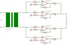
I have some designing problems with mij bridge clone,
I`am using a jensen JT-11p-1 input transformer as a buffer.
which drives (+ and -) a total of 4 non-inverted lm3886`s
can the scematic (pic) be used as it is?
what resistor values do i need for best impendance matching?
R1= 1K?(riken ohm)
What resistor values for R2,R3? (22k , 680R vishay s102)
My powersupply wil be a 2X22v= 500va torroid
R4=0,22ohm dale
Maybe Kuei Yang Wang can help me on the trafo thing......
Menno
Attachments
- Status
- Not open for further replies.
- Home
- Amplifiers
- Chip Amps
- Bridgeclone