The low drop is one consideration and try and find one with a very low reverse capacitance.
The Baker-clamp simply removes drive current (and voltage) from the transistor's base and therefore prevents saturation
A saturated transistor can't be switched off as fast as an unsaturated one because there is more charge to be removed from the base than necessary.
Cheers all,
Thats just the kind of explaination i needed to hear. I knew it was altering the base current in some way but i didn't think it was going that far! I see why everybody who uses this type of driver arragement seems to be controlling it with a constant current, if you dont the clamp diode will send all the tranys current back to the signal source effectivly shorting it out!
Thanks again,
Mad.P
Schmatics
Hi all,
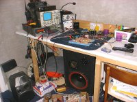
I've prepared the schematics for the new oscillating amp, also got some piccys of it for your amusment. Take a look and let me know what you think
The amp is still in test configuration using a single rail 12V supply. You will notice the 6n137 opto couplers in there. I now have my hands on some high speed magnetic couplers. These will be in by the end of the week and i will also convert to split rail when the drivers are proved to be reliable. The sound as it sounds is fantastic, it can only get better!
Have fun!
Mad.P
Hi all,
I've prepared the schematics for the new oscillating amp, also got some piccys of it for your amusment. Take a look and let me know what you think
The amp is still in test configuration using a single rail 12V supply. You will notice the 6n137 opto couplers in there. I now have my hands on some high speed magnetic couplers. These will be in by the end of the week and i will also convert to split rail when the drivers are proved to be reliable. The sound as it sounds is fantastic, it can only get better!
Have fun!
Mad.P
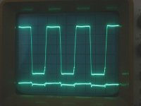
Here you have a view of the high side fet's gate wavform along with post filter bridge output ripple below it. The scopes timebase is set to 500ns per division and 5V per division for the switching waveform, 1 volt per division for the ripple. The bridge waveform is identical to that of the high side gate drive. The scope is referenced to ground so befor any of you tell me i'm ramming 24 volts into the gate remember that the whole of the high side fet is bouncing up and down along with its bootstrap riding on the bridge output wavform.
Attachments
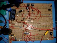
Here i present the schematic of the front end of the amplifier. If you look at the circuit you will notice a very large dead time has been programmed. I have done this to eliminate shoot-through on the fets caused by a massive 100n/s delay in the optos. The programmed time will be reduced considerabley when i exchange the optos for magnetic couplers😀
Attachments
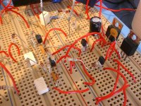
And finally the buisness part of the amp. Not much to say here, it seems perfectly stable at the mo, i've been using the amp in this state over the past few days now without any problems. The sound quality is crystal with surprising helpings of bass for the size of the supply. The noise floor is so low that there is virtually no noticable hiss when operated in open loop mode. Distortion has yet to be determined but i cant detect any at all just by listening with my ears. The comparater and pre-amp or lack of them will be inserted later when i split the supply. I have some high speed comparaters from maxim waiting.. also some new op-amps from the same source. I think that the amp will be a mighty warrior after all this is done........ Let me know of your thoughts....
Take care all,
Mad.P
Take care all,
Mad.P
Attachments
Hi Nitrate,
There's several anti saturation techniques which can be used, but the one known as "baker clamp" employs a schottky. If you want to use sic diodes at least two are required.
I'd expect more noise and heating when you go beyond 12V, or +-6V, but this is an excellent start.
Looking forward to more.
Regards,
Chris
It's mainly harmonics or distortion of waveform, related to slow speed of output stage (ton/toff >100ns ); modifying the output stage gives a big difference.
I wonder if the device could run linear, the comparator's input stage must have been saturated during such high frequency / large signal.
I wonder if the device could run linear, the comparator's input stage must have been saturated during such high frequency / large signal.
subwo1 said:I think the problem could have something to do with the feedback loop if the amp is able to operate smoothly from the 10s of Hz to several MHz range. There could also be things like circuit layout and noise which begins to detract from clean high frequency operation.
BEWARE....
The schematic i posted for the amps front end has an error,
I forgot to include an inverter in the lower fet drive. This is one of the spare logic inverters and must be used in between the lower fet drive inverter as drawn and the opto it is wired to. As it stands now the fets will both be on at the same time LOL
I'm off now to hunt for good de-saturaton techniques on google.
See ya's
Mad.P
Am i imagining things?
I think the placebo affect is playing tricks on me
Last night i swapped the optos in my amp for some high speed IL711 devices ( magnetic couplers ). Things were a lot quicker and faster but i could not get my descrete driver stage to loose an annoying 100n/s propogation delay so i cheated i little and pulled all the little tranys and diodes out replacing them with the maxim MAX626 ( for experimental purposes 😉 ). I powered up and found a very quick fast switching drive to the fets with a propogation of around 50n/s. The total delay both for rise and fall was now around 100n/s, even on both sides. This allowed me to finally lower my dead time down to 50n/s. Should sound good thought i..... I put on some famililar music only to find in my opinion the sound was worse than with the optos!. Could it be true or am i a victim to my own persistence? As they say if you look for faults you will always find them. Has anyone else tried these magnetic couplers? If so did they effect your sound? In theory they sould not be able to effect the sound as they are just part of a two state signal. How can this be that the slower optos and discrete driver sounded better than this sharp high speed drive stage? As far as i know the magnetic couplers don't have an internal clock, and my bridge signal has very little ringing or other distortions. The frequency of oscillation is now set to 900KHz ( I don't wanna go faster ).
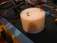
I also found out my lovley air core coil needs more inductance as my amp has slightly more gain at 20K Than the lower freqs and abouve 15K things start to get more triangular rarther than sine.
Oh well my journey continues........ Is the grass greener on the other side?
Mad.P
I think the placebo affect is playing tricks on me
Last night i swapped the optos in my amp for some high speed IL711 devices ( magnetic couplers ). Things were a lot quicker and faster but i could not get my descrete driver stage to loose an annoying 100n/s propogation delay so i cheated i little and pulled all the little tranys and diodes out replacing them with the maxim MAX626 ( for experimental purposes 😉 ). I powered up and found a very quick fast switching drive to the fets with a propogation of around 50n/s. The total delay both for rise and fall was now around 100n/s, even on both sides. This allowed me to finally lower my dead time down to 50n/s. Should sound good thought i..... I put on some famililar music only to find in my opinion the sound was worse than with the optos!. Could it be true or am i a victim to my own persistence? As they say if you look for faults you will always find them. Has anyone else tried these magnetic couplers? If so did they effect your sound? In theory they sould not be able to effect the sound as they are just part of a two state signal. How can this be that the slower optos and discrete driver sounded better than this sharp high speed drive stage? As far as i know the magnetic couplers don't have an internal clock, and my bridge signal has very little ringing or other distortions. The frequency of oscillation is now set to 900KHz ( I don't wanna go faster ).
I also found out my lovley air core coil needs more inductance as my amp has slightly more gain at 20K Than the lower freqs and abouve 15K things start to get more triangular rarther than sine.
Oh well my journey continues........ Is the grass greener on the other side?
Mad.P
Kenshin said:It's mainly harmonics or distortion of waveform, related to slow speed of output stage (ton/toff >100ns ); modifying the output stage gives a big difference.
Speeding up the transition is a good way to lower distortion if the switching timing is not near hard-to-obtain perfection.
Kenshin said:I wonder if the device could run linear, the comparator's input stage must have been saturated during such high frequency / large signal.
I think it depends a lot on whether the driver stage is is fast enough and has enough gain.

nitrate said:Am i imagining things?
I think the placebo affect is playing tricks on me
Last night i swapped the optos in my amp for some high speed IL711 devices ( magnetic couplers ). Things were a lot quicker and faster but i could not get my descrete driver stage to loose an annoying 100n/s propogation delay so i cheated i little and pulled all the little tranys and diodes out replacing them with the maxim MAX626 ( for experimental purposes 😉 ). I powered up and found a very quick fast switching drive to the fets with a propogation of around 50n/s. The total delay both for rise and fall was now around 100n/s, even on both sides. This allowed me to finally lower my dead time down to 50n/s. Should sound good thought i..... I put on some famililar music only to find in my opinion the sound was worse than with the optos!. Could it be true or am i a victim to my own persistence? As they say if you look for faults you will always find them. Has anyone else tried these magnetic couplers? If so did they effect your sound? In theory they sould not be able to effect the sound as they are just part of a two state signal. How can this be that the slower optos and discrete driver sounded better than this sharp high speed drive stage? As far as i know the magnetic couplers don't have an internal clock, and my bridge signal has very little ringing or other distortions. The frequency of oscillation is now set to 900KHz ( I don't wanna go faster ).
Mad.P
This result tends to support the notion I had that a well-timed fast linear amp made to work in classD may do better than a faster one using more high-low switching.
Fixed it!
The bad sound i was on about was indeed due to things being a little too quick. The RF was bleeding through my output filter causing dodgey sound. Even though the frequency was switching higher than before, the RF was being helped along through my filter due to very fast square switch edges on the bridge. The slightly untidy layout on the breadboard did not help either To get around this i first tidied up the layout on the board and doubled the inductance of the air coil. This stoped the RF in its tracks but caused massive ringing as the fets switch even faster. I considered slowing them down and getting them to switch a bit sloppy to remidi things but in the end i decided to try a snubber network to see how effective it would be at getting rid of the ringing. This proved to be a good idea as 22R+1nF on each of the fets completly killed the ringing. After a listening test i conlude that the audio quality is back to 'Stunning'. Truley the best i've had things yet.
I'm glad i've spent the last 6 month building various amps as normally i work with nothing but digital, MCU's logic and the like. I used to hate the thought of messing with analougy stuff but playing with these amps has been a real learning experience for me. I've learnt about crowbar currents, fet transconductance, transistor saturation, subbers, decouplers, filters but to name a few of the things. I'm just lovin it😀
Mad.P
The bad sound i was on about was indeed due to things being a little too quick. The RF was bleeding through my output filter causing dodgey sound. Even though the frequency was switching higher than before, the RF was being helped along through my filter due to very fast square switch edges on the bridge. The slightly untidy layout on the breadboard did not help either
To get around this i first tidied up the layout on the board and doubled the inductance of the air coil. This stoped the RF in its tracks but caused massive ringing as the fets switch even faster. I considered slowing them down and getting them to switch a bit sloppy to remidi things but in the end i decided to try a snubber network to see how effective it would be at getting rid of the ringing. This proved to be a good idea as 22R+1nF on each of the fets completly killed the ringing. After a listening test i conlude that the audio quality is back to 'Stunning'. Truley the best i've had things yet. I'm glad i've spent the last 6 month building various amps as normally i work with nothing but digital, MCU's logic and the like. I used to hate the thought of messing with analougy stuff but playing with these amps has been a real learning experience for me. I've learnt about crowbar currents, fet transconductance, transistor saturation, subbers, decouplers, filters but to name a few of the things. I'm just lovin it😀
Mad.P
I've learnt about crowbar currents, fet transconductance, transistor saturation, subbers, decouplers, filters but to name a few of the things. I'm just lovin it
Another soul that went lost forever ........ ! 😀
Regards
Charles
Wow..... I need a quieter CD player 😀
Hello all,
Just a quick update about whats been happening and also a question i need advise on. Since my last post my amp has become so quiet that the noise floor of my cheap CD player is now becoming offensive. Also the amp has such a low noise floor itself for the first time ever i can now clearly hear the noise floor of my graphic equaliser, and that really quiet! Anyway my amp now is running off split +-12v supplies, uses magnetic couplers along with maxim fet drivers for the output drive, uses a maxim high presision comparator for the sig-delta modulation. I have limited the amp to 600KHz in the modulator stage to avoid excessive ringing in the output and excessive heat generation in the bootstrap diode along with other stuff. I still use both pre and post feedback, pre mainly for the oscillation and stability and post just to help with the frequency response. Everything seems very stable and rock solide. Sound is very very nice with next to no background ( i expected it to go up with split rail and larger volts but it has not changed ). The post feedback does introduce a very slight kink in part of the sine but i'm trying to find the cause of this to eliminate it. if it can't be cured i may do away with the post feedback. The amp clips very gracefully with no tendency to go unstable/shake or gitter. It just goes flat on the top of the sine🙂 The input impedence is fairly low at around 5K so i'm using large input capacitanc to stop bass being attenuated but i plan to use an op-amp just as an input buffer. I'm off work next week so i'll adjust the amp for the big supply and give it a go. If it works well i'll make a proper PCB and get two in a case😀
Anyway my question.......
How do you measure THD at home? I belive you can use the PC soundcard?? The equipment i have that may help is the following :-
Sig-gen 0-1Meg sine/Square
Function gen 0-1Ghz
Scope
various multimeters
Freq counter
I can also borrow a spectrum analyser from work but its not very good.
Can i measure THD with what i have? Hopefully it can simply be done using the sig-gen and soundcard.
Regards
Mad.P
Hey all,
haven't posted for a while, been busy being ill and doing long-winded and generally uninteresting research into locating and silencing noise in my amp so i havn't bored you all with the details. I have it licked now, full power ( 150 watts ) with no audible hiss or distortion at all, even at idle. 4V peak-peak sensitivity to 150watts, completly flat freq response across spectrum from DC to 25Khz. Anyway, i'm gonna make a stereo version soon, but before i dissapear for a while whilst i lay out the pcbs i have an interesting thought that may invoke some discussion.
I was observing a phenomenom with my amp were the heatsink would remain cool for ages, but if i abused the amp and warmed the sink up it would stay luke warm thereafter until i either switch it off or force cool it. I think that using fets in the input stage is working against us here. If you think back to times when amps used to suffer from thermal runaway the transisters gain increased with temp hence the hotter the amp the harder it worked causing even more heat! This was largly cured by the use of fets in amps. These back off as temp increase so the hotter the amp the less the fets conduct so it cools down again. Everybody thought this was good at the time, indeed it was as it greatly stablised the amps and did away with the nessesity of temp stablisation circuits. Our class d amps you would think don't suffer from this problem but actually they do. We look for low RDS on in our fets, and because of this the amps run very cool as the fet is always hard on or off. When the amp actually does manage to heat up however the RDS on is going to increase causing more heat and bingo... we have thermal runaway once more!! It probably won't cause a problem as the effect is much more surpressed then it used to be in the old AB amps, however the fact that it has returned to haunt us is really quite annoying and in very high power amps may just be a concern. What do you think about this? Do you think it is anything to bother worrying about?
Take care all,
Mad.P
nitrate said:Hey all,
haven't posted for a while, been busy being ill and doing long-winded and generally uninteresting research into locating and silencing noise in my amp so i havn't bored you all with the details. I have it licked now, full power ( 150 watts ) with no audible hiss or distortion at all, even at idle. 4V peak-peak sensitivity to 150watts, completly flat freq response across spectrum from DC to 25Khz. Anyway, i'm gonna make a stereo version soon, but before i dissapear for a while whilst i lay out the pcbs i have an interesting thought that may invoke some discussion.
I was observing a phenomenom with my amp were the heatsink would remain cool for ages, but if i abused the amp and warmed the sink up it would stay luke warm thereafter until i either switch it off or force cool it. I think that using fets in the input stage is working against us here. If you think back to times when amps used to suffer from thermal runaway the transisters gain increased with temp hence the hotter the amp the harder it worked causing even more heat! This was largly cured by the use of fets in amps. These back off as temp increase so the hotter the amp the less the fets conduct so it cools down again. Everybody thought this was good at the time, indeed it was as it greatly stablised the amps and did away with the nessesity of temp stablisation circuits. Our class d amps you would think don't suffer from this problem but actually they do. We look for low RDS on in our fets, and because of this the amps run very cool as the fet is always hard on or off. When the amp actually does manage to heat up however the RDS on is going to increase causing more heat and bingo... we have thermal runaway once more!! It probably won't cause a problem as the effect is much more surpressed then it used to be in the old AB amps, however the fact that it has returned to haunt us is really quite annoying and in very high power amps may just be a concern. What do you think about this? Do you think it is anything to bother worrying about?
Take care all,
Mad.P
I dunno, sounds like you require more convection cooler/bigger heatsink or more air floor. Mosfets dont' always have a positive temp co but for class d they do. If Rds on rises when temp increases, as a result less current flows, as a result thermal run away can't occure. It's also not going to happen unless you have them paralleled.
Regards,
Chris
- Status
- Not open for further replies.
- Home
- Amplifiers
- Class D
- Breadboard Class D!!